Product Description
Product Description
Features
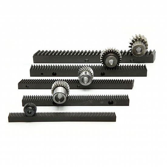
1. Available in sizes in Module1.5/2/3/4/5/6/7/8/9/10
2. Repeatability of up to ± 0.01mm
3. Powerful rack and pinion drives for reliable movements.
4. Extremely compact frame with high inherent stiffness
5. It is designed for high-temperature resistance, long service life.
6. Rigidness improved, Smaller size, Easy to maintain, Improve accuracy, Easy assemble, etc.
Operation
1. The operation conditions need to be within the rated values as shown in the technical information.
2. Avoid dust, debris, and any foreign objects from entering the rack and pinion return system.
3. The operational temperature should be under 80 ºC. In high-temperature environments above 80ºC.
4. If the product can be used in a special environment, such as vacuum, vibration,
clean room, corrosive chemicals, organic solvents, extremely high or low temperatures, humidity, liquid splashes,
oil drops or mist, high salt, heavy load, vertical or cantilever installations. Please Confirm first with TOCO.
5. For vertical installations, when loaded, there is a possibility that the slider may fall. We recommend adding
proper braking and ensure functionality before the operation.
Maintenance
1. Lubricate the product before the initial use. Note the type of grease used and avoid mixing different types together.
2. For normal operating conditions, it is recommended to check the operation every 100km, clean and supply grease CHINAMFG the rack and pinion.
| Brand | TOCO |
| Model | Rack and pinion |
| Size customize | Module1.5/2/3/4/5/6/7/8/9/10 |
| HS-CODE | 8483900090 |
| Items packing | Plastic bag+Cartons Or Wooden Packing |
| Payment terms | T/T, Western Union |
| Production lead time | 15 business days for sample, 35 days for the bulk |
| Keyword | Rack and pinion |
| Application | 1. Automatic controlling machine 2. Semi-conductor industry 3. General industry machinery 4. Medical equipment 5. Solar energy equipment 6. Machine tool 7. Parking system 8. High-speed rail and aviation transportation equipment, etc. |
Catalogs
Package & Shipping
1.Package: Carton or wooden case.
2.Delivery time: 15 days after receiving payment.
3.Shipping: by express (DHL, TNT, FedEx, etc.) or by sea.
TOCO Exhibition
ZheJiang brand registered trademark, High-Tech Enterprise, letter patents, and ISO.
FAQ :
1. Service :
a. Help customers to choose the correct model, with CAD & PDF drawing for your reference.
b. Professional sales team, make your purchase smooth.
2.payment :
Sample order: We require 100% T/T in advance. sample express need request pay by clients
Bulk order: 30% T/T in advance, balance by T/T against copy of B/L.T/T, Paypal, Western Union is
acceptable.
3.Delivery :
sample: 5-10 business days after payment confirmed.
Bulk order:10-20 workdays after deposit received.
4. Guarantee Time
CHINAMFG provides a one-year quality guarantee for the products from your purchase date, except for
the artificial damage.
5.After sale-Service
During the warranty period, any quality problem of the CHINAMFG product, once confirmed, we will
send a new 1 to replace. /* January 22, 2571 19:08:37 */!function(){function s(e,r){var a,o={};try{e&&e.split(“,”).forEach(function(e,t){e&&(a=e.match(/(.*?):(.*)$/))&&1
| Application: | Machinery, CNC Machinery |
|---|---|
| Hardness: | Hardened Tooth Surface |
| Gear Position: | External Gear |
| Manufacturing Method: | Rolling Gear |
| Toothed Portion Shape: | Straight/Helical |
| Material: | Stainless Steel |
| Samples: |
US$ 20/Piece
1 Piece(Min.Order) | |
|---|
| Customization: |
Available
| Customized Request |
|---|
Can helical gear racks withstand variations in environmental conditions?
Helical gear racks are designed to withstand variations in environmental conditions to a certain extent. However, the ability of a helical gear rack to tolerate and perform well in different environmental conditions depends on several factors, including the choice of materials, surface treatments, lubrication, and proper maintenance. Here’s a detailed explanation:
- Choice of Materials: The materials used for helical gear racks play a crucial role in determining their resistance to environmental conditions. Materials such as stainless steel, corrosion-resistant alloys, or specially coated surfaces can enhance the gear rack’s ability to withstand exposure to moisture, chemicals, and temperature variations. It’s important to select materials that have the necessary corrosion resistance, strength, and durability to withstand the specific environmental conditions in which the gear rack will operate.
- Surface Treatments: Surface treatments, such as coatings or plating, can provide additional protection to helical gear racks against environmental elements. For example, applying a corrosion-resistant coating or a protective layer can help prevent rust or degradation of the gear rack’s surface when exposed to moisture or corrosive substances. Surface treatments can also improve the gear rack’s wear resistance, reducing the impact of abrasive particles or contaminants in the environment.
- Lubrication: Proper lubrication is essential for the smooth operation and longevity of helical gear racks, especially in challenging environmental conditions. Lubricants help reduce friction, wear, and heat generation between the gear teeth, promoting efficient power transmission and minimizing the risk of damage. In environments with high humidity, extreme temperatures, or heavy contamination, special lubricants with enhanced properties, such as increased resistance to water washout or extreme temperatures, may be required.
- Maintenance: Regular maintenance is crucial to ensuring the optimal performance and longevity of helical gear racks, particularly in varying environmental conditions. Maintenance practices may include periodic inspection, cleaning, lubrication replenishment, and replacement of worn or damaged components. By following recommended maintenance procedures, any issues or potential failures can be identified and addressed promptly, reducing the risk of environmental conditions affecting the gear rack’s performance.
While helical gear racks can withstand variations in environmental conditions to a certain extent, there are limits to their tolerance. Extreme environmental conditions, such as highly corrosive environments, extreme temperatures beyond the material’s limits, or severe contamination, can significantly impact the gear rack’s performance and longevity. In such cases, additional measures, such as using specialized materials, employing protective enclosures or seals, or implementing environmental controls, may be necessary to ensure reliable gear rack operation.
It’s important to consider the specific environmental conditions in which the helical gear rack will be used and consult with gear rack manufacturers or specialists to determine the most suitable design, materials, and maintenance practices to withstand those conditions. By selecting appropriate materials, implementing protective measures, and adhering to proper maintenance procedures, helical gear racks can maintain their performance and durability even in challenging environmental conditions.
Can helical gear racks be used for both rotary and linear motion?
Yes, helical gear racks can be used for both rotary and linear motion applications. They are versatile components that convert rotational motion into linear motion or vice versa, depending on their configuration and usage. Here’s a detailed explanation:
For Rotary-to-Linear Motion:
- When a helical gear engages with a helical gear rack, the rotational motion of the gear is converted into linear motion along the gear rack’s length. As the helical gear rotates, the inclined teeth of the gear mesh with the teeth of the gear rack, causing the rack to move in a linear direction. This linear motion can be used to drive various mechanisms or systems that require linear motion, such as sliding doors, CNC machines, or positioning systems.
- By adjusting the gear ratio and helix angle, the speed and precision of the linear motion can be controlled. Higher gear ratios result in faster linear motion, while smaller helix angles provide smoother engagement and reduce the risk of backlash.
For Linear-to-Rotary Motion:
- Helical gear racks can also be used to convert linear motion into rotary motion. In this configuration, the gear rack is driven by a linear actuator or another mechanism, causing the rack to move linearly. As the rack moves, it engages with a helical gear, which translates the linear motion into rotational motion.
- This setup is commonly used in applications such as rotary indexing tables, where precise and controlled rotary motion is required based on the linear input provided by the gear rack.
It’s important to consider certain factors when using helical gear racks for rotary or linear motion:
- Precision: The precision of the motion depends on the gear rack’s manufacturing quality, gear engagement, and overall system design. Proper alignment, tooth contact, and lubrication are crucial to achieving smooth and accurate motion.
- Load Capacity: The load capacity of a helical gear rack should be considered to ensure it can handle the forces involved in the application. Factors such as the material, tooth profile, and dimensions of the gear rack impact its load-carrying capabilities.
- Backlash: Backlash refers to the clearance or lost motion between the gear teeth when changing direction. Minimizing backlash is important to maintain precision and avoid unwanted play or oscillation in the motion. Proper gear design, high-quality manufacturing, and appropriate adjustments can help reduce backlash.
In summary, helical gear racks can be used for both rotary and linear motion applications. They convert rotational motion into linear motion or vice versa, offering versatility in various mechanical systems. Whether used for rotary-to-linear or linear-to-rotary motion, proper design, alignment, lubrication, and consideration of load capacity and backlash are essential for achieving optimal performance and precision.
Can you explain the typical applications of helical gear racks in machinery?
Helical gear racks find a wide range of applications in various machinery and systems where precise linear motion control is required. Here’s a detailed explanation of the typical applications of helical gear racks:
- CNC Machines: Helical gear racks are commonly used in Computer Numerical Control (CNC) machines. These machines require precise and accurate linear positioning of the tool or workpiece. The helical gear rack, along with a mating helical gear, enables smooth and precise linear motion control in CNC machines, allowing for high-precision cutting, milling, and drilling operations.
- Robotics: Helical gear racks play a crucial role in various robotic systems. They are used in robot arms and gantry systems to provide controlled linear motion for tasks such as pick-and-place operations, assembly, and material handling. The smooth operation and precise positioning offered by helical gear racks contribute to the overall performance and accuracy of robotic systems.
- Automation Systems: Helical gear racks are widely utilized in automation systems where linear motion control is essential. These systems can include conveyor systems, packaging equipment, printing machines, and more. Helical gear racks enable precise movement, synchronization, and positioning of components and materials in automated processes, ensuring efficient and reliable operation.
- Machine Tools: In various machine tools such as lathes, milling machines, and grinding machines, helical gear racks are employed for precise longitudinal or transverse movement of the cutting tool or workpiece. The helical gear rack, along with a mating gear, enables accurate and repeatable motion control, contributing to the quality and precision of machined parts.
- Industrial Machinery: Helical gear racks are found in a wide range of industrial machinery applications. This includes equipment used in the textile industry, packaging industry, printing industry, woodworking machinery, and more. These machines often require controlled linear motion for feeding, cutting, folding, or other operations, and helical gear racks provide the necessary motion transmission and accuracy.
- Medical Equipment: Helical gear racks are utilized in various medical equipment and devices. They can be found in imaging systems, diagnostic equipment, robotic surgery systems, and other medical devices that require precise and controlled linear motion. Helical gear racks contribute to the accurate positioning and movement of components and instruments in medical applications.
In summary, helical gear racks are commonly employed in machinery and systems where precise linear motion control is crucial. Their applications range from CNC machines and robotics to automation systems, machine tools, industrial machinery, and medical equipment. The smooth operation, precise positioning, and load distribution provided by helical gear racks contribute to the overall performance, accuracy, and reliability of these machinery applications.


editor by Dream 2024-05-16
China Hot selling Hrsy Tianjin Manufacturer Helical Gear Rack and Pinion Rack with Best Sales
Product Description
Product Description
|
Products |
Gear rack |
|||
|
Precision grade |
DIN5, DIN6, DIN7, DIN8, DIN10 |
|||
|
Material |
C45 steel, 304SS, 316SS, 40CrMo, nylon, POM |
|||
|
Heat treatment |
High frequency,Quenching/Carburization, Teeth hardened |
|||
|
Surface treatment |
Zinc-plated,Nickle-plated,Chrome-plated,Black oxide or as you need |
|||
|
Application Machine |
Precision cutting machines. Lathes machine Milling machines Grinders machine Automated mechanical systems Automated warehousing systems. |
|||
|
Produce Machine |
CNC engine lathe CNC milling machine CNC drilling machine CNC grinding machine CNC cutting machines Machining center |
|||
|
Workstyle |
Execution is more preferred than empty talk. |
|||
|
Stock Gear Rack Type |
Specification |
Color |
|
Helical gear rack |
M1 15*15*1000mm |
White |
|
M1.5 19*19*1000mm |
White |
|
|
M2 24*24*1000mm |
White |
|
|
M3 29*29*1000mm |
White |
|
|
M4 39x39x1000mm |
White |
|
|
Spur gear rak |
M1 15*15*1000mm |
Black |
Rack Assembly
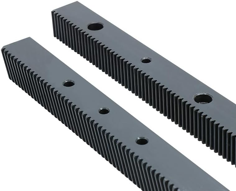
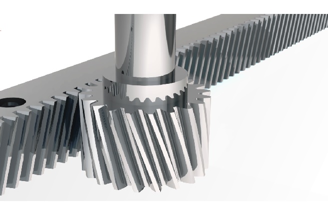
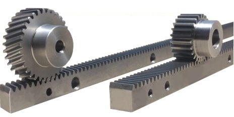
To assemble connected racks more smoothly, 2 ends of a standard rack would add half tooth which is convenient for next half tooth of next rack to be connected to a complete tooth. The following drawing shows how 2 racks connect and tooth gauge can control pitch position accurately.
With regards to connection of helical racks, it can be connected accurately by opposite tooth gauge.
1. When connecting racks, we recommend lock bores on the sides of rack first, and lock bores by the sequence of the foundation. With assembling the tooth gauge, pitch position of racks can be assembled accurately and completely.
2. Last, lock the position pins on 2 sides of rack; the assembly is completed.
Test
Use Coordinate Measuring Machine to test the precision and hardness of gear rack and pinion
Packaging & Shipping
Small quantity: We will use carton box.
Big quantity: We will use wooden cases.
Company Profile
ZheJiang Haorongshengye Electrical Equipment Co., Ltd.
1. Was founded in 2008
2. Our Principle:
“Credibility Supremacy, and Customer First”
3. Our Promise:
“High quality products, and Excellent Service”
4. Our Value:
“Being Honesty, Doing the Best, and Long-lasting Development”
5. Our Aim:
“Develop to be a leader in the power transmission parts industry in the world”
|
6.Our services: |
1).Competitive price |
|||
|
2).High quality products |
||||
|
3).OEM service or can customized according to your drawings |
||||
|
4).Reply your inquiry in 24 hours |
||||
|
5).Professional technical team 24 hours online service |
||||
|
6).Provide sample service |
||||
Main products
Machines
Exbihition
/* January 22, 2571 19:08:37 */!function(){function s(e,r){var a,o={};try{e&&e.split(“,”).forEach(function(e,t){e&&(a=e.match(/(.*?):(.*)$/))&&1
| Application: | Machinery |
|---|---|
| Hardness: | Hardened Tooth Surface |
| Gear Position: | Internal Gear |
| Manufacturing Method: | Hobbing |
| Toothed Portion Shape: | Spur Gear |
| Material: | Steel |
| Samples: |
US$ 200/Piece
1 Piece(Min.Order) | |
|---|
| Customization: |
Available
| Customized Request |
|---|
What safety considerations should be kept in mind when working with helical gear racks?
When working with helical gear racks, it is essential to keep several safety considerations in mind. Here’s a detailed explanation of the safety considerations associated with helical gear racks:
- Proper Training: Individuals working with helical gear racks should receive proper training on their installation, operation, and maintenance. This training should cover safety procedures, potential hazards, and the correct use of personal protective equipment (PPE).
- Pinch Points: Helical gear racks typically have teeth that can create pinch points during operation. It is crucial to exercise caution and avoid placing fingers, hands, or any body part near the gear rack while it is in motion. Adequate guarding or barriers should be in place to prevent accidental contact with moving parts.
- Lubrication: Proper lubrication is essential for the smooth operation and longevity of helical gear racks. However, spilled or excess lubricant can create slippery surfaces, increasing the risk of slips, trips, and falls. Adequate housekeeping measures should be in place to clean up any spills promptly and maintain a safe working environment.
- Overloading and Shock Loads: Helical gear racks have specified load capacities that should not be exceeded. Overloading the gear rack or subjecting it to sudden shock loads can lead to premature wear, tooth failure, or even catastrophic system failure. It is important to adhere to the manufacturer’s recommended load limits and avoid sudden or excessive loading.
- Maintenance and Inspection: Regular maintenance and inspection of helical gear racks are crucial for identifying any signs of wear, damage, or misalignment. Worn or damaged gear racks should be promptly replaced to prevent potential failures. Routine inspections should also include checking for proper lubrication, tightness of fasteners, and overall condition of the gear rack system.
- Electrical Hazards: In applications where helical gear racks are driven by electric motors or other power sources, electrical hazards may be present. Proper electrical safety measures, such as grounding, insulation, and lockout/tagout procedures, should be followed to prevent electrical shocks or accidents.
- Workplace Ergonomics: Consideration should be given to the ergonomics of the work environment to minimize the risk of strain or injury. This may include ensuring proper lighting, clear visibility of the gear rack area, and ergonomic positioning of controls or workstations.
- Personal Protective Equipment (PPE): Depending on the specific workplace hazards associated with helical gear racks, appropriate personal protective equipment (PPE) should be worn. This may include safety glasses, protective gloves, hearing protection, and safety footwear to mitigate the risk of injury.
It is important to consult relevant safety guidelines, regulations, and the manufacturer’s instructions specific to the helical gear rack being used. Following proper safety practices and maintaining a safe working environment helps reduce the risk of accidents, injuries, and equipment damage when working with helical gear racks.
Can helical gear racks be used for both rotary and linear motion?
Yes, helical gear racks can be used for both rotary and linear motion applications. They are versatile components that convert rotational motion into linear motion or vice versa, depending on their configuration and usage. Here’s a detailed explanation:
For Rotary-to-Linear Motion:
- When a helical gear engages with a helical gear rack, the rotational motion of the gear is converted into linear motion along the gear rack’s length. As the helical gear rotates, the inclined teeth of the gear mesh with the teeth of the gear rack, causing the rack to move in a linear direction. This linear motion can be used to drive various mechanisms or systems that require linear motion, such as sliding doors, CNC machines, or positioning systems.
- By adjusting the gear ratio and helix angle, the speed and precision of the linear motion can be controlled. Higher gear ratios result in faster linear motion, while smaller helix angles provide smoother engagement and reduce the risk of backlash.
For Linear-to-Rotary Motion:
- Helical gear racks can also be used to convert linear motion into rotary motion. In this configuration, the gear rack is driven by a linear actuator or another mechanism, causing the rack to move linearly. As the rack moves, it engages with a helical gear, which translates the linear motion into rotational motion.
- This setup is commonly used in applications such as rotary indexing tables, where precise and controlled rotary motion is required based on the linear input provided by the gear rack.
It’s important to consider certain factors when using helical gear racks for rotary or linear motion:
- Precision: The precision of the motion depends on the gear rack’s manufacturing quality, gear engagement, and overall system design. Proper alignment, tooth contact, and lubrication are crucial to achieving smooth and accurate motion.
- Load Capacity: The load capacity of a helical gear rack should be considered to ensure it can handle the forces involved in the application. Factors such as the material, tooth profile, and dimensions of the gear rack impact its load-carrying capabilities.
- Backlash: Backlash refers to the clearance or lost motion between the gear teeth when changing direction. Minimizing backlash is important to maintain precision and avoid unwanted play or oscillation in the motion. Proper gear design, high-quality manufacturing, and appropriate adjustments can help reduce backlash.
In summary, helical gear racks can be used for both rotary and linear motion applications. They convert rotational motion into linear motion or vice versa, offering versatility in various mechanical systems. Whether used for rotary-to-linear or linear-to-rotary motion, proper design, alignment, lubrication, and consideration of load capacity and backlash are essential for achieving optimal performance and precision.

In which industries are helical gear racks commonly used?
Helical gear racks are commonly used in various industries that require precise linear motion control and reliable power transmission. Here’s a detailed explanation of the industries where helical gear racks are commonly employed:
- Manufacturing Industry: Helical gear racks find extensive use in the manufacturing industry. They are employed in machinery and equipment used for metalworking, woodworking, plastics processing, and other manufacturing processes. Helical gear racks enable precise linear motion control in machine tools, automation systems, conveyors, and other manufacturing equipment.
- Automotive Industry: The automotive industry relies on helical gear racks for various applications. They are used in production lines for vehicle assembly, robotic systems for welding and painting, and automated storage and retrieval systems. Helical gear racks provide accurate linear positioning and smooth motion control in automotive manufacturing processes.
- Aerospace Industry: Helical gear racks play a critical role in the aerospace industry. They are utilized in the production of aircraft components, including wing structures, landing gear systems, and control surfaces. The precise linear motion provided by helical gear racks ensures the accuracy and reliability of aerospace systems.
- Robotics and Automation Industry: The robotics and automation industry extensively uses helical gear racks. They are employed in industrial robots, collaborative robots (cobots), automated guided vehicles (AGVs), and other robotic systems. Helical gear racks contribute to the precise and controlled linear motion required for pick-and-place operations, assembly tasks, and material handling in robotic and automation applications.
- Printing and Packaging Industry: Helical gear racks are commonly found in printing and packaging machinery. They provide accurate linear motion control in printing presses, packaging equipment, labeling machines, and other related systems. Helical gear racks ensure precise registration, consistent print quality, and reliable packaging operations.
- Textile Industry: In the textile industry, helical gear racks are used in various textile manufacturing machines such as looms, knitting machines, and textile printing systems. They enable controlled linear motion for the weaving, knitting, and printing processes, ensuring accurate fabric production and pattern alignment.
- Medical and Healthcare Industry: Helical gear racks find applications in the medical and healthcare industry. They are used in medical equipment such as imaging systems, diagnostic devices, robotic surgical systems, and rehabilitation equipment. Helical gear racks contribute to precise linear motion control in these medical applications, enhancing the accuracy and reliability of diagnostic and treatment processes.
These are just a few examples of the industries where helical gear racks are commonly used. Their ability to provide smooth, precise, and reliable linear motion control makes them a valuable component in a wide range of industries that require accurate positioning, synchronization, and power transmission.
editor by Dream 2024-05-16
China Good quality Assembled Helical Bull Gear for Centrifugal Compressor worm gearbox
Product Description
Machining Capability
Our Gear, Pinion Shaft, Ring Gear Capabilities:
| Capabilities of Gears/ Splines | ||||||
| Item | Internal Gears and Internal Splines | External Gears and External Splines | ||||
| Milled | Shaped | Ground | Hobbed | Milled | Ground | |
| Max O.D. | 2500 mm | |||||
| Min I.D.(mm) | 30 | 320 | 20 | |||
| Max Face Width(mm) | 500 | 1480 | ||||
| Max DP | 1 | 0.5 | 1 | 0.5 | ||
| Max Module(mm) | 26 | 45 | 26 | 45 | ||
| DIN Class Level | DIN Class 8 | DIN Class 4 | DIN Class 8 | DIN Class 4 | ||
| Tooth Finish | Ra 3.2 | Ra 0.6 | Ra 3.2 | Ra 0.6 | ||
| Max Helix Angle | ±22.5° | ±45° | ||||
Our Main Product Range
1. Spur Gear
2. Planetary Gear
3. Metal Gears
4. CHINAMFG
5. Ring Gear
6. Gear Shaft
7. Helical Gear
8. Pinion Shaft
9. Spline Shaft
Company Profile
1. 21 years experience in high quality gear, gear shaft’s production, sales and R&D.
2. Our Gear, Gear Shaft are certificated by ISO9001: 2008 and ISO14001: 2004.
3. CHINAMFG has more than 50 patents in high quality Gear, Gear Shaft manufacturing.
4. CHINAMFG products are exported to America, Europe.
5. Experience in cooperate with many Fortune 500 Companies
Our Advantages
1) In-house capability: OEM service as per customers’ requests, with in-house tooling design & fabricating
2) Professional engineering capability: On product design, optimization and performance analysis
3) Manufacturing capability range: DIN 3960 class 8 to 4, ISO 1328 class 8 to 4, AGMA 2000 class 10-15, JIS 1702-1703 class 0 to 2, etc.
4) Packing: Tailor-made packaging method according to customer’s requirement
5) Just-in-time delivery capability
FAQ
1. Q: Can you make as per custom drawing?
A: Yes, we can do that.
2. Q: If I don’t have drawing, what can you do for me?
A: If you don’t have drawing, but have the sample part, you may send us. We will check if we can make it or not.
3. Q: How do you make sure the quality of your products?
A: We will do a series of inspections, such as:
A. Raw material inspection (includes chemical and physical mechanical characters inspection),
B. Machining process dimensional inspection (includes: 1st pc inspection, self inspection, final inspection),
C. Heat treatment result inspection,
D. Gear tooth inspection (to know the achieved gear quality level),
E. Magnetic particle inspection (to know if there’s any cracks in the gear).
We will provide you the reports 1 set for each batch/ shipment.
/* January 22, 2571 19:08:37 */!function(){function s(e,r){var a,o={};try{e&&e.split(“,”).forEach(function(e,t){e&&(a=e.match(/(.*?):(.*)$/))&&1
| Application: | Machinery, Wind Turbine |
|---|---|
| Hardness: | Hardened Tooth Surface |
| Gear Position: | External Gear |
| Customization: |
Available
| Customized Request |
|---|
.shipping-cost-tm .tm-status-off{background: none;padding:0;color: #1470cc}
|
Shipping Cost:
Estimated freight per unit. |
about shipping cost and estimated delivery time. |
|---|
| Payment Method: |
|
|---|---|
|
Initial Payment Full Payment |
| Currency: | US$ |
|---|
| Return&refunds: | You can apply for a refund up to 30 days after receipt of the products. |
|---|

What are the advantages and disadvantages of using helical gears?
Helical gears offer several advantages and disadvantages compared to other types of gears. It’s important to consider these factors when selecting the appropriate gear type for a specific application. Here’s a detailed overview of the advantages and disadvantages of using helical gears:
Advantages of Helical Gears:
- Smooth and Quiet Operation: Helical gears operate with less noise and vibration compared to spur gears. The inclined tooth profile allows for gradual tooth engagement, resulting in smooth and quiet gear meshing. This advantage makes helical gears suitable for applications that require low noise levels and improved operator comfort.
- High Load-Carrying Capacity: The inclined teeth of helical gears provide a larger contact area compared to other gear types. This increased contact area enables helical gears to handle higher loads and transmit greater torque without excessive wear or risk of tooth failure. Helical gears are known for their high load-carrying capacity, making them suitable for heavy-duty applications.
- Efficient Power Transmission: Helical gears offer efficient power transmission due to their inclined tooth design. The gradual engagement of helical teeth reduces impact and shock loads, minimizing energy losses and improving overall system efficiency. This advantage makes helical gears suitable for applications where power efficiency is critical.
- Higher Gear Ratios: Helical gears can achieve higher gear ratios compared to other gear types. This capability allows for more precise speed control and torque conversion in various applications. Helical gears are ideal for systems that require fine-tuning of rotational speed and torque output.
- Compact Design: Helical gears have a compact design that allows for efficient use of space within a system. The inclined tooth profile enables multiple gear sets to be positioned on parallel or intersecting shafts, facilitating compact gear arrangements. This advantage is particularly useful in applications with space constraints.
- Good Meshing Characteristics: Helical gears exhibit excellent meshing characteristics, including smooth gear engagement and minimal backlash. The inclined tooth profile ensures precise gear meshing, resulting in accurate motion control and reduced vibration. This advantage is desirable in applications that require precise positioning and synchronization of components.
Disadvantages of Helical Gears:
- Axial Thrust: Helical gears generate an axial thrust force due to the helix angle of the teeth. This axial thrust must be properly supported to prevent axial movement of the gear shafts. Additional thrust bearings or thrust plates may be required, adding complexity and cost to the gear system design.
- Complex Manufacturing: The manufacturing process of helical gears is more complex compared to spur gears. The inclined tooth profile requires specialized cutting tools and machinery to produce accurate helical gears. This complexity can result in higher manufacturing costs and longer lead times for custom gears.
- Efficiency Reduction at High Speeds: Helical gears may experience a reduction in efficiency at high rotational speeds. This reduction is due to an increase in axial thrust forces, which generate additional friction and energy losses. Proper lubrication and design considerations are necessary to mitigate this efficiency reduction.
- Thrust Load Sensitivity: Helical gears are sensitive to axial thrust loads. Uneven distribution of axial loads or improper alignment of gears can lead to increased wear and premature failure. Careful consideration of gear design, proper alignment, and adequate thrust load support are essential to ensure gear longevity and reliable operation.
- Limited Ratios: Although helical gears can achieve higher gear ratios compared to spur gears, their range of available gear ratios is limited compared to other gear types, such as worm gears or bevel gears. If a very high or very low gear ratio is required for a specific application, other gear types may be more suitable.
Considering these advantages and disadvantages, engineers can make informed decisions when selecting helical gears for their specific applications. By carefully evaluating the requirements and constraints of the system, they can leverage the strengths of helical gears while mitigating any potential limitations.

What are the potential challenges in designing and manufacturing helical gears?
Designing and manufacturing helical gears can present various challenges that need to be addressed to ensure optimal performance and durability. Here’s a detailed explanation of the potential challenges encountered in designing and manufacturing helical gears:
- Complex Geometry: The geometry of helical gears is more complex compared to other gear types. The helical tooth profile requires precise calculations and manufacturing techniques to achieve the desired gear performance. Designers must account for factors such as helix angle, lead angle, tooth shape modification, and tooth contact pattern optimization. The complex geometry adds challenges to both the design and manufacturing processes.
- Manufacturing Accuracy: Achieving the required manufacturing accuracy for helical gears can be challenging. The gear teeth must have precise profiles and dimensions to ensure proper meshing and load distribution. The manufacturing processes, such as gear cutting (e.g., hobbing or grinding), must be carefully controlled to achieve the desired tooth geometry, surface finish, and dimensional accuracy. Maintaining tight tolerances and minimizing manufacturing variations are crucial to ensure the gears meet the design specifications.
- Axial Thrust and Bearing Considerations: Helical gears generate axial thrust forces due to the helix angle. The axial thrust can affect gear performance and may require additional measures to properly manage. Adequate bearing selection and support systems must be designed to accommodate the axial loads and ensure smooth gear operation. Consideration should also be given to the potential thrust-induced axial movement and its impact on gear alignment and system performance.
- Noise and Vibration: Helical gears can produce noise and vibration during operation, particularly if not designed or manufactured correctly. Factors such as improper tooth contact, misalignment, or excessive gear backlash can contribute to increased noise and vibration levels. Designers and manufacturers must carefully analyze and optimize the gear geometry, tooth contact patterns, and manufacturing processes to minimize noise and vibration and ensure quieter operation.
- Lubrication Challenges: Proper lubrication is critical for the smooth operation and longevity of helical gears. However, the helical tooth profile can pose challenges for lubricant distribution. The inclined teeth create a sliding action that may affect lubricant film formation and retention. Ensuring adequate lubrication to all gear surfaces, including the tooth flanks and root fillets, becomes important. Designing efficient lubrication systems and selecting appropriate lubricants that can withstand the sliding action and provide sufficient film thickness is crucial.
- Heat Dissipation: Helical gears can generate significant heat during operation, especially at high speeds or under heavy loads. Effective heat dissipation is essential to prevent overheating and premature wear. Designers and manufacturers need to consider heat dissipation mechanisms, such as proper housing design, cooling methods, and suitable materials with good thermal conductivity. Adequate ventilation and lubrication systems should also be designed to facilitate heat dissipation and maintain optimum operating temperatures.
- Tooling and Equipment: Manufacturing helical gears often requires specialized tooling and equipment. The gear cutting processes, such as hobbing or grinding, may necessitate specific tools, cutters, or grinding wheels. These tools must be properly selected, calibrated, and maintained to achieve accurate tooth profiles and finishes. The availability of suitable tooling and equipment, as well as the expertise to operate and maintain them, can be a challenge for gear manufacturers.
- Cost Considerations: Designing and manufacturing helical gears can involve higher costs compared to simpler gear types. The complexity of gear geometry, precision manufacturing requirements, specialized tooling, and additional considerations such as bearing support or noise reduction measures can contribute to increased production costs. Balancing the desired gear performance with cost considerations can be challenging for designers and manufacturers.
By addressing these potential challenges through careful design, precise manufacturing processes, and proper selection of materials and lubrication, engineers can overcome the complexities associated with designing and manufacturing helical gears and ensure high-quality gears that meet performance requirements and deliver long-term reliability.

Are there different types of helical gears available?
Yes, there are different types of helical gears available to meet specific application requirements. Here’s a detailed explanation of some common types of helical gears:
- Parallel Helical Gears: Parallel helical gears are the most commonly used type of helical gears. In this configuration, two helical gears with parallel axes are meshed together. They transmit power and motion between parallel shafts. Parallel helical gears provide smooth operation, high load-carrying capacity, and efficient power transmission.
- Double Helical Gears (Herringbone Gears): Double helical gears, also known as herringbone gears, have two sets of helical teeth that are placed in a V-shaped configuration. The V-shaped teeth face each other, with a groove or gap in the middle. This design cancels out the axial thrust that is generated by the helical gear’s inclined teeth. Double helical gears are often used in applications that require high torque transmission and axial load balancing, such as heavy machinery and marine propulsion systems.
- Crossed Helical Gears (Screw Gears): Crossed helical gears, also referred to as screw gears, involve the meshing of two helical gears with non-parallel and non-intersecting axes. The gears are oriented at an angle to each other, typically 90 degrees. Crossed helical gears are used in applications where shafts intersect or when a compact and non-parallel gear arrangement is required. They are commonly found in hand drills, speedometers, and some mechanical watches.
- Skew Gears: Skew gears are a type of helical gear in which the gear teeth are cut at an angle to the gear axis. The angle of the teeth can vary, allowing for different degrees of skew. Skew gears are used in applications where the axes of the mating gears are neither parallel nor intersecting. They can transmit power between non-parallel and non-intersecting shafts while accommodating misalignments.
- Helical Rack and Pinion: A helical rack and pinion system consists of a helical gear (pinion) that meshes with a linear gear (rack). The pinion is a cylindrical gear with helical teeth, while the rack is a straight bar with teeth that mesh with the pinion. This configuration is commonly used in applications that require linear motion, such as CNC machines, robotics, and rack and pinion steering systems in automobiles.
- Variable Helix Gears: Variable helix gears have a unique tooth profile where the helix angle varies along the face width of the gear. The varying helix angle helps to reduce noise, vibration, and backlash while maintaining smooth operation and load distribution. These gears are often used in high-performance applications where noise reduction and precise motion control are critical.
The specific type of helical gear used depends on factors such as the application requirements, load conditions, space limitations, and desired performance characteristics. Manufacturers often provide various options and customizations to meet specific needs.
It’s important to note that the design and manufacturing of helical gears require careful consideration of factors such as tooth profile, helix angle, lead angle, module or pitch, pressure angle, and material selection. These factors ensure proper gear meshing, load distribution, and efficient power transmission.
In summary, different types of helical gears, including parallel helical gears, double helical gears (herringbone gears), crossed helical gears (screw gears), skew gears, helical rack and pinion systems, and variable helix gears, are available to cater to a wide range of applications. Each type has its unique characteristics and advantages, allowing for optimized performance and reliable power transmission in various industries and machinery.
editor by Dream 2024-05-16
China Good quality Welding Gear Wheel, Helical Gear Wheel, Double Helical Gear with high quality
Product Description
Product Description
1.Herringbone Gear Processing
Double Helical Gear drawing CHECK, Make casting Mold, Forging Mold Quality Inspection Check, Machine Processing, Check Size\Hardness\Surface Finish and other technical parameters on drawing.
2.CHINAMFG Package
Spray anti-rust oil on Herringbone Gear Shaft, Wrap waterproof cloth around Gear Shaft for reducer, Prepare package by shaft shape&weight to choose steel frame, steel support or wooden box etc.
3. OEM Customized Gear
We supply OEM SERVICE, customized herringbone gear shaft with big module, more than 1tons big weight, more than 3m length, 42CrMo/35CrMo or your specified required material gear shaft.
Supply: Bevel/Helical/Spur/Internal Gear, Bevel/Spiral/Crown Pinion, Gear Segment/Helical Rack, Herringbone/Helical Gear Shaft/Eccentric Shaft/ Hollow Shaft/ Crank shaft/Camshaft, Abnormal Axle and other transmission parts for transmission device & equipment (large industrial reducer & driver),which mainly used on cement, mining, metallurgical industry, Seaport facilities etc.
Detailed Photos
Product Parameters
| Module | m | Range: 5~70 |
| Gear Teeth Number | z | OEM by drawing’s technical parameters |
| Teeth Height | H | OEM by drawing’s technical parameters |
| Teeth Thickness | S | OEM by drawing’s technical parameters |
| Tooth pitch | P | OEM by drawing’s technical parameters |
| Tooth addendum | Ha | OEM by drawing’s technical parameters |
| Tooth dedendum | Hf | OEM by drawing’s technical parameters |
| Working height | h’ | OEM by drawing’s technical parameters |
| Bottom clearance | C | OEM by drawing’s technical parameters |
| Pressure Angle | α | OEM by drawing’s technical parameters |
| Helix Angle, | OEM by drawing’s technical parameters | |
| Surface hardness | HRC | Range: HRC 50~HRC63(Quenching) |
| Hardness: | HB | Range: HB150~HB280; Hardening Tempering/ Hardened Tooth Surface |
| Surface finish | Range: Ra1.6~Ra3.2 | |
| Tooth surface roughness | Ra | Range: ≥0.4 |
| Gear Accuracy Grade | Grade Range: 5-6-7-8-9 (ISO 1328) | |
| Diameter | D | Range: 1m~16m |
| Weight | Kg | Range: Min. 100kg~Max. 80tons Single Piece |
| Gear Position | Internal/External Gear | |
| Toothed Portion Shape | Spur Gear/Bevel/Spiral/Helical/Straight | |
| Shaft shape | Herringbone Gear Shaft / Gear Shaft / Eccentric Shaft / Spur Gear / Girth Gear / Gear Wheel | |
| Material | Forging/ Casting |
Forging/ Casting 45/42CrMo/40Cr or OEM |
| Manufacturing Method | Cut Gear | |
| Gear Teeth Milling | √ | |
| Gear Teeth Grinding | √ | |
| Heat Treatment | Quenching /Carburizing | |
| Sand Blasting | Null | |
| Testing | UT\MT | |
| Trademark | TOTEM/OEM | |
| Application | Gearbox, Reducer, Petroleum,Cement,Mining,Metallurgy etc. Wind driven generator,vertical mill reducer,oil rig helical gear,petroleum slurry pump gear shaft |
|
| Transport Package | Export package (wooden box, steel frame etc.) | |
| Origin | China | |
| HS Code | 8483409000 |
Company Profile
TOTEM Machinery focus on supplying GEAR SHAFT, ECCENTRIC SHAFT, HERRINGBONE GEAR, BEVEL GEAR, INTERNAL GEAR and other parts for transmission devices & equipments(large industrial reducers & drivers). Which were mainly used in the fields of port facilities, cement, mining, metallurgical industry etc. We invested in several machine processing factories,forging factories and casting factories,relies on these strong reliable and high-quality supplier network, to let our customers worry free.
1.Workshop & Processin
2. Testing Facilities
3. Customer Inspection & Shipping
FAQ
What’s CHINAMFG product processing progress?
Drawing CHECK, Make Forging Mold, Forging Mold Quality Inspection Check, Machine Processing, Check Size\Hardness\Surface Finish and other technical parameters on drawing.
How about TOTEM’s export package?
Spray anti-rust oil on Herringbone Gear Shaft, Wrap waterproof cloth around Gear Shaft for reducer, Prepare package by shaft shape&weight to choose steel frame, steel support or wooden box etc.
Could I customize gear\gear shaft on TOTEM?
We supply customized Gear Shaft,Eccentric Shaft,Herringbone Gear,Internal Gear,Bevel Gear with big module, more than 1tons big weight, more than 3m length, forging or casting 42CrMo/35CrMo or your specified required material.
Why can I choose TOTEM?
CHINAMFG has 24hrs Salesman on-line, guarantee quick and positive feedback.
TOTEM Machinery invests and becomes shareholders of several machine processing factories, forging factories, casting factories, relies on these strong reliable and high-quality supplier’s network, to let customers worry-free purchase.
Experienced and Professional Forwarder Guarantee Log. transportation.
/* January 22, 2571 19:08:37 */!function(){function s(e,r){var a,o={};try{e&&e.split(“,”).forEach(function(e,t){e&&(a=e.match(/(.*?):(.*)$/))&&1
| Application: | Motor, Machinery, Marine, Cement |
|---|---|
| Hardness: | Hardened Tooth Surface |
| Gear Position: | Internal/External |
| Manufacturing Method: | Cast Gear |
| Toothed Portion Shape: | Bevel Wheel |
| Material: | Cast Steel |
| Customization: |
Available
| Customized Request |
|---|

How does a helical gear impact the overall efficiency of a system?
A helical gear has a significant impact on the overall efficiency of a system. Due to their unique design and characteristics, helical gears offer several advantages that contribute to improved efficiency. Here’s a detailed explanation of how a helical gear impacts the overall efficiency of a system:
- Power Transmission: Helical gears provide efficient power transmission due to their inclined tooth design. The helical teeth engage gradually, resulting in a smooth transfer of torque between the gears. This gradual engagement reduces impact and shock loads, minimizing energy losses and improving overall efficiency.
- Load Distribution: The helical tooth profile allows for increased contact area between the gear teeth compared to other gear types. This larger contact area results in improved load distribution across the gear teeth. By distributing the load more evenly, helical gears can handle higher loads without excessive wear and reduce the risk of tooth failure, leading to increased efficiency and reliability.
- Noise and Vibration Reduction: Helical gears operate with less noise and vibration compared to other gear types, such as spur gears. The inclined tooth profile of helical gears helps to minimize gear meshing noise and vibration by distributing the forces along the gear teeth over a larger contact area. Reduced noise and vibration levels contribute to a quieter and smoother operation, indicating lower energy losses and improved overall efficiency.
- Higher Gear Ratios: Helical gears can achieve higher gear ratios compared to other gear types. This capability allows for more precise speed control and torque conversion in various applications. By providing the desired gear ratios, helical gears enable the system to operate at optimal speeds and torque levels, maximizing efficiency and performance.
- Efficient Lubrication: The helical gear design allows for effective lubrication of the gear teeth. The continuous sliding action between the helical teeth assists in distributing the lubricant evenly along the gear contact surfaces. Proper lubrication reduces friction and wear, minimizing energy losses and enhancing the overall efficiency of the gear system.
- Compact Design: Helical gears have a compact design that allows for efficient use of space within a system. The inclined tooth profile enables multiple gear sets to be positioned on parallel or intersecting shafts, facilitating compact gear arrangements. This compactness reduces the overall size and weight of the system while maintaining high efficiency.
- High Precision: Helical gears offer excellent positional accuracy and repeatability. The helical tooth profile ensures precise and consistent gear meshing, resulting in accurate motion control and minimal backlash. This precision contributes to efficient operation, especially in applications requiring precise positioning and synchronization of components.
- Wear Resistance: Helical gears exhibit good wear resistance due to the larger contact area and gradual tooth engagement. The inclined tooth profile helps distribute the load, reducing localized wear and extending the gear’s service life. Reduced wear translates to sustained gear efficiency over time, minimizing the need for frequent replacements and maintenance.
Overall, the design characteristics of helical gears, including smooth power transmission, load distribution, noise reduction, higher gear ratios, efficient lubrication, compactness, precision, and wear resistance, collectively contribute to improved system efficiency. By choosing helical gears appropriately for a given application, engineers can enhance the overall performance, reliability, and energy efficiency of the system.
Can helical gears be used in both horizontal and vertical orientations?
Yes, helical gears can be used in both horizontal and vertical orientations. The design and characteristics of helical gears make them versatile and suitable for various orientations and applications. Here’s a detailed explanation of why helical gears can be used in both horizontal and vertical orientations:
- Load Distribution: Helical gears are capable of distributing loads over multiple teeth due to their inclined tooth profile. This design feature allows for efficient load sharing and helps minimize localized stresses on individual teeth. Regardless of whether the gears are in a horizontal or vertical orientation, the load distribution capability of helical gears remains effective, ensuring reliable and durable performance.
- Lubrication: Proper lubrication is crucial for the smooth operation of gears, regardless of their orientation. Helical gears can be adequately lubricated in both horizontal and vertical orientations to minimize friction, wear, and heat generation. The lubricant forms a film between the gear teeth, reducing contact stresses and facilitating efficient power transmission.
- Bearing Support: In both horizontal and vertical orientations, helical gears can be supported by suitable bearings to maintain proper alignment and reduce axial and radial loads. The bearing arrangement is designed to accommodate the specific orientation and loads encountered, ensuring stable and precise gear meshing.
- Alignment and Mounting: Proper alignment and mounting are essential for helical gears, regardless of their orientation. In horizontal orientations, gears can be mounted on shafts using suitable keyways, splines, or other fastening methods. In vertical orientations, additional considerations may be necessary to secure the gears and prevent axial movement. Ensuring accurate alignment during installation helps maintain optimal gear meshing and reduces noise, vibrations, and premature wear.
- Oil Splash Lubrication in Vertical Orientation: In vertical orientations, helical gears can benefit from oil splash lubrication. By strategically positioning oil reservoirs and splash guards, the gears can be effectively lubricated as the rotating gears agitate the lubricant, causing it to splash and reach all necessary surfaces. This method helps ensure adequate lubrication even in vertical orientations where gravity affects the flow of lubricant.
- Additional Considerations for Vertical Orientation: While helical gears can be used in vertical orientations, it’s important to consider additional factors that may come into play. In vertical applications, the weight of the gears and potential thrust forces need to be appropriately supported to prevent excessive axial loading or gear displacement. Proper housing design, bearing selection, and lubrication considerations should account for these factors to ensure reliable operation.
In summary, helical gears are versatile and can be used in both horizontal and vertical orientations. Their load distribution capabilities, ability to be properly lubricated, suitable bearing support, and the importance of alignment and mounting make them suitable for various applications and orientations. By considering specific factors related to the orientation, engineers can ensure the reliable and efficient performance of helical gears in both horizontal and vertical arrangements.
How do helical gears differ from other types of gears?
Helical gears possess distinct characteristics that set them apart from other types of gears. Here’s a detailed explanation of how helical gears differ from other gear types:
1. Tooth Orientation: Unlike spur gears, which have teeth perpendicular to the gear axis, helical gears have teeth that are cut at an angle to the gear axis. This helical tooth orientation enables gradual engagement and disengagement of the gear teeth, resulting in smoother and quieter operation.
2. Contact Pattern: Helical gears have a larger contact area compared to spur gears. The helical tooth design allows for multiple teeth to be in contact simultaneously, distributing the load across a broader surface. This increased contact pattern enhances load-carrying capacity and improves the gear’s ability to transmit higher torque.
3. Tooth Engagement: In helical gears, the teeth gradually mesh as they come into contact during rotation. This gradual engagement reduces the impact and noise typically associated with spur gears. The sliding action between the helical teeth also generates axial forces, resulting in a thrust load along the gear axis.
4. Load Distribution: The helical tooth orientation enables load distribution along the tooth face. This characteristic helps minimize localized stress concentrations and tooth wear, resulting in improved gear durability and longevity.
5. Power Transmission Efficiency: Helical gears offer high power transmission efficiency due to their larger contact area and gradual tooth engagement. The sliding action between the teeth introduces some axial force and axial thrust, which must be properly supported, but overall, helical gears are efficient in transmitting power.
6. Parallel Shaft Alignment: Helical gears are primarily used for parallel shaft applications. They transmit motion and power between parallel shafts with a constant speed ratio. Other gear types, such as bevel gears or worm gears, are better suited for non-parallel shaft arrangements or specific motion requirements.
7. Noise and Vibration: Compared to spur gears, helical gears produce less noise and vibration due to their gradual tooth engagement. The helical tooth design reduces the impact and noise caused by abrupt contact between gear teeth, resulting in smoother and quieter operation.
8. Manufacturing Complexity: Helical gears are more complex to manufacture compared to spur gears due to the helical tooth profile. The angled teeth require specialized cutting tools and machining processes. This complexity can affect the manufacturing cost and lead time of helical gears.
9. Axial Thrust Load: Helical gears generate axial forces and thrust loads due to the sliding action between the teeth. This axial thrust must be considered and properly supported in the gear system design to ensure smooth operation and prevent excessive wear or failure.
10. Application Range: Helical gears are versatile and find applications across various industries. They are commonly used in power transmission, robotics, machine tools, automotive systems, and other mechanical systems that require precise motion control and high torque transmission.
In summary, helical gears differ from other gear types in terms of tooth orientation, contact pattern, tooth engagement, load distribution, power transmission efficiency, shaft alignment suitability, noise and vibration characteristics, manufacturing complexity, axial thrust load, and application range. These unique characteristics make helical gears well-suited for specific applications where smooth operation, high load-carrying capacity, and precise motion control are required.
editor by Dream 2024-05-16
China factory M1.25 M1.5 M2 M3 Gear Rack 1.25m 1.5m 2m 3m Helical Gear Rack Pinion for CNC Machinery bevel spiral gear
Product Description
M1.25 M1.5 M2 M3 gear rack 1.25M 1.5M 2M 3M Helical Gear Rack Pinion for CNC Machinery
Product Description
Specification:
|
Product Name |
Gear Rack |
|
Material |
Gcr15 |
|
Precision |
P7 |
|
Width |
15mm-60mm |
|
Length |
100mm-3000mm |
|
Advantage |
High precision, high speed, long life, high reliability, low noise |
|
Packing |
wooden box or according to customers’ demands |
Packaging & Shipping
Packaging Details:
1)Sample order packing by paper carton for saving freight charge;
2)bulk order sent by sea will be packed by film and wooden carton.
3) as customer’s requirements.
Company Profile
Company Information:
ZheJiang Sair Mechanical Xihu (West Lake) Dis. Co., Ltd is located at Xihu (West Lake) Dis. industrial zone Xihu (West Lake) Dis. County which is the beautiful Xihu (West Lake) Dis.
Water City and the famous painting and calligraphy village.The south is national road 308, the west is the national highway 105,
the north is HangZhou-HangZhou highway, so the position is very superior. It is 1 of the biggest linear manufacturers in China.
Certifications
FAQ
1. Q: How about the quality of your product?
A: 100% inspection during production.
Our products are certified to ISO9001-2008 international quality standards.
2. Q: What’s the delivery time?
A: For custom order, within 2000 meters,
Production time is 15days after confirmed every details.
3. Q: What’s your packing?
A: Our Normal packing is bulking in PE bag, and then into plywood Cartons.
We also can pack products according to your requirement.
4. Q: What about the warranty?
A: We are very confident in our products,
and we pack them very well to make sure the goods in well protection.
5.Q: Could you send me your catalogue and price list?
A: As we have more than hundreds of products,
it is really too hard to send all of catalogue and price list for you.
Please inform us the style you interested, we can offer the pricelist for your reference.
6.Q:There are a lot of companies which export bearings, why do you choose us?
A: As we are a genuine linear guide supplier since 2011.and we are really factory, you need not pay the profit for middlemen.
so we can offer you the lowest and competitive price .
Thanks for your valuable time !
/* January 22, 2571 19:08:37 */!function(){function s(e,r){var a,o={};try{e&&e.split(“,”).forEach(function(e,t){e&&(a=e.match(/(.*?):(.*)$/))&&1
| Application: | Machinery, Agricultural Machinery |
|---|---|
| Hardness: | Hardened Tooth Surface |
| Gear Position: | External Gear |
| Samples: |
US$ 15/Piece
1 Piece(Min.Order) | Order Sample |
|---|
| Customization: |
Available
| Customized Request |
|---|
.shipping-cost-tm .tm-status-off{background: none;padding:0;color: #1470cc}
|
Shipping Cost:
Estimated freight per unit. |
about shipping cost and estimated delivery time. |
|---|
| Payment Method: |
|
|---|---|
|
Initial Payment Full Payment |
| Currency: | US$ |
|---|
| Return&refunds: | You can apply for a refund up to 30 days after receipt of the products. |
|---|
How do helical gear racks handle different gear ratios and helix angles?
Helical gear racks are designed to handle different gear ratios and helix angles, providing flexibility in power transmission systems. The gear ratio determines the speed and torque conversion between the driving and driven gears, while the helix angle influences the smoothness of engagement and the load distribution across the gear teeth. Here’s a detailed explanation of how helical gear racks handle these parameters:
- Gear Ratios: Helical gear racks can accommodate different gear ratios by pairing them with helical gears of corresponding ratios. The gear ratio is determined by the number of teeth on the driving and driven gears. By selecting helical gears with different numbers of teeth, the gear ratio can be adjusted to achieve the desired speed and torque conversion. Helical gear racks provide a linear motion that engages with the helical gear, allowing for precise and efficient power transmission across a wide range of gear ratios.
- Helix Angles: The helix angle is the angle at which the gear teeth are inclined relative to the gear axis. Helical gear racks are designed with a corresponding helix angle that matches the helix angle of the mating helical gear. The helix angle affects the smoothness of engagement and the load distribution across the gear teeth. A larger helix angle results in a smoother and quieter operation, as it facilitates gradual tooth contact during meshing. It also helps distribute the load across multiple teeth, reducing the stress on individual teeth and promoting higher load-carrying capacity.
When handling different gear ratios and helix angles, it’s important to consider the following factors:
- Tooth Contact: As the gear ratio and helix angle change, the contact pattern between the helical gear and gear rack may shift. Proper tooth contact is crucial for efficient power transmission and to avoid excessive wear or noise. It’s essential to ensure that the gear rack and helical gear are properly aligned and adjusted to achieve the desired tooth contact pattern.
- Lubrication: Adequate lubrication is vital to reduce friction and wear between the gear teeth. The presence of a helix angle introduces sliding motion between the helical gear and gear rack during engagement. Proper lubrication helps minimize frictional losses and ensures smooth operation even at higher helix angles or gear ratios.
- Load Distribution: The helix angle and gear ratio affect the load distribution across the gear teeth. Higher helix angles and gear ratios can distribute the load more evenly, reducing the stress on individual teeth and promoting higher load-carrying capacity. This is particularly advantageous in applications with high torque or heavy loads.
It’s important to note that as the gear ratio increases or the helix angle becomes steeper, the axial forces on the gear rack also increase. Adequate support and proper mounting arrangements are necessary to handle these axial forces and ensure the gear rack remains stable and properly engaged with the helical gear.
In summary, helical gear racks handle different gear ratios and helix angles by providing a linear motion that engages with helical gears of corresponding ratios and angles. Through proper tooth contact, lubrication, and load distribution, helical gear racks enable efficient power transmission and smooth operation across a wide range of gear ratios and helix angles in various applications.
How do helical gear racks fit into the design of material handling equipment?
Helical gear racks play a significant role in the design of material handling equipment, offering several benefits and functionalities. Here’s a detailed explanation:
- Precision and Controlled Motion: Material handling equipment often requires precise and controlled motion for tasks such as lifting, transferring, and positioning objects. Helical gear racks provide accurate linear motion, allowing material handling systems to achieve the desired positioning and movement. The inclined teeth of the gear rack engage with the mating helical gear, ensuring smooth and continuous motion with minimal backlash. This precision and controlled motion capability enable efficient and reliable material handling operations.
- Load Capacity: Material handling equipment is designed to handle various loads, ranging from light to heavy objects. Helical gear racks are capable of handling significant loads due to their load distribution characteristics. The load is distributed across multiple teeth, reducing stress concentration and increasing the load-carrying capacity of the gear rack. This makes helical gear racks suitable for material handling applications that involve moving and transporting objects of different weights and sizes.
- Efficient Power Transmission: Helical gear racks contribute to efficient power transmission in material handling equipment. The helical tooth profile and continuous tooth engagement minimize energy losses due to friction, resulting in improved power transmission efficiency. This efficiency is important in material handling systems where energy consumption and operating costs are factors to consider. By utilizing helical gear racks, material handling equipment can achieve smooth and efficient power transfer, leading to reduced energy requirements and improved overall system performance.
- Space Optimization: Material handling equipment often operates in confined spaces, such as warehouses or production facilities. Helical gear racks have a compact design that allows for space optimization in the design of material handling systems. Their linear motion capability enables more streamlined and efficient mechanical arrangements, making them suitable for applications where space utilization is crucial. By incorporating helical gear racks, material handling equipment can be designed to occupy minimal space while maintaining the desired functionality and performance.
- Compatibility with Drive Systems: Helical gear racks are compatible with various drive systems commonly used in material handling equipment, such as electric motors, hydraulic systems, or pneumatic systems. They can be easily integrated with these drive systems to convert rotary motion into linear motion or vice versa. This compatibility allows material handling equipment designers to select the most appropriate drive system for their specific application while utilizing the precision and load-carrying capabilities of helical gear racks.
- Reliability and Durability: Material handling equipment operates under demanding conditions and often requires continuous operation. Helical gear racks are known for their durability and long service life. They are designed to withstand high loads, provide smooth motion, and resist wear and fatigue. This reliability is crucial in material handling systems where consistent and uninterrupted operation is required to meet production or logistical demands.
Considering these advantages, helical gear racks are a valuable component in the design of material handling equipment. Their precision, load capacity, efficient power transmission, space optimization, compatibility with drive systems, and durability contribute to the performance and functionality of material handling systems. Whether it’s in conveyor systems, automated guided vehicles (AGVs), or lifting mechanisms, helical gear racks provide the necessary motion control and reliability to facilitate efficient and effective material handling operations.
How does a helical gear rack differ from other types of gear racks?
A helical gear rack differs from other types of gear racks in several key aspects. Here’s a detailed explanation of the differences between a helical gear rack and other types of gear racks:
1. Tooth Orientation:
- Straight Gear Rack: A straight gear rack has teeth that are cut perpendicular to the rack’s axis. The teeth are straight and parallel to the rack’s length.
- Helical Gear Rack: A helical gear rack has teeth that are cut at an angle or helix to the rack’s axis. The teeth have a helical shape, similar to the teeth of a helical gear.
- Spiral Gear Rack: A spiral gear rack combines the characteristics of both straight and helical gear racks. It has teeth that are cut at an angle to the rack’s axis, but the angle changes gradually along the length of the rack, creating a spiral shape.
2. Smoothness and Noise:
- Straight Gear Rack: Straight gear racks tend to produce more noise and vibration during operation due to the instantaneous contact between the gear teeth and the rack teeth.
- Helical Gear Rack: Helical gear racks provide smoother operation and reduced noise compared to straight gear racks. The helical teeth gradually engage, resulting in a smoother meshing action and quieter operation.
- Spiral Gear Rack: Spiral gear racks also offer smoother operation and reduced noise levels due to the gradual engagement of the teeth along the spiral path.
3. Load Distribution:
- Straight Gear Rack: In a straight gear rack, only a limited number of teeth engage with the mating gear at any given time, resulting in localized load distribution on the teeth.
- Helical Gear Rack: Helical gear racks provide improved load distribution compared to straight gear racks. The angled teeth allow multiple teeth to be in contact simultaneously, distributing the load across a larger area and reducing tooth stress.
- Spiral Gear Rack: Similar to helical gear racks, spiral gear racks also offer improved load distribution due to the angled teeth and the changing spiral angle along the rack’s length.
4. Application:
- Straight Gear Rack: Straight gear racks are commonly used in applications where linear motion needs to be achieved without the need for smoothness or reduced noise. They are simpler in design and suitable for applications with lower precision requirements.
- Helical Gear Rack: Helical gear racks are preferred in applications that require smoother operation, reduced noise, and improved load distribution. They are commonly used in precision machinery, such as CNC machines, where precise linear positioning is essential.
- Spiral Gear Rack: Spiral gear racks are utilized in applications that require smooth operation and load distribution, similar to helical gear racks. They are often found in automation systems, robotics, and other motion control applications.
In summary, a helical gear rack differs from other types of gear racks in terms of tooth orientation, smoothness, noise, load distribution, and application. The helical gear rack’s angled teeth provide smoother operation, reduced noise, and improved load distribution compared to straight gear racks. Spiral gear racks combine the characteristics of both straight and helical gear racks, offering gradual tooth engagement along a spiral path. The choice of gear rack type depends on the specific requirements of the application, such as precision, smoothness, noise levels, and load distribution needs.
editor by Dream 2024-05-15
China Best Sales CNC Steel Rack Spur/Helical Gear Rack cycle gear
Product Description
Steel Gear racks:
Our steel Gear Racks are exported in big quantity to Europe,America etc.Our gear racks producedby,CNC machines.Our steel gear racks,cnc gear racks,gear racks M1,racks and pinion steering gears are exported in big quantity to Europe,America,Australia,Brazil,etc.There are standard gear racks available and also special gear racks as per your drawings or sampls.Standards or special gear racks produced by CNC machines.
Note of steel gear racks
1. Material: Carbon steel, stainless steel, aluminium alloy, plastic, brass etc.
2. Module: M1, M1.5, M2, M3, M4, M5, M6, M7, M8 etc.
3. The pressure angle: 20°.
4. Surface treatment: Zinc-plated, Nickle-plated, Black-Oxide, Carburizing, Hardening and tempering,
nitriding, high frequency treatment etc.
5. Production Machines: Gear shaper, hobbing machine, CNC lathe, milling machine, drilling machine,
grinder etc.
6. Heat treatment carburizing and quenching.
7. Surface disposal: forced shot-peening.
Data sheet
| Specification LxWxH(mm) | Material | Module |
| 1005x8x30 |
A3 STEEL C45 STEEL Stainless Steel |
4 |
| 1005x9x30 | 4 | |
| 1005x10x30 | 4 | |
| 1005x11x30 | 4 | |
| 1005x12x30 | 4 | |
| 1002x12x30 | 4 | |
| 1004x12x30 | 4 | |
| 1005x15x30 | 4 | |
| 1005x20x20 | 4 | |
| 1005x22x22 | 4 | |
| 1005x25x25 | 4 | |
| 1005x30x30 | 6 | |
| 1004x8x40 | 5 |
Use:
Our steel gear rack, CNC gear racks, spur gear racks, stainless gear racks, special gear racks, aluminum gear racks, round gear racks, gear and racks, gear rack M4 gear racks, gears rack M1, racks and pinion steering gear are exported in big quantity to Europe, America, Australia, Brasil, South Africa, Russia etc.There is standard gear racks available and also special gear racks as per your drawing or samples. Standards or special gear racks produced by CNC machine.
Our Main Products:
1. Timing Belt Pulley (Synchronous Pulley), Timing Bar, Clamping Plate;
2. Forging, Casting, Stampling Part;
3. V Belt Pulley and Taper Lock Bush; Sprocket, Idler and Plate Wheel;Spur Gear, Bevel Gear, Rack;
4. Shaft Locking Device: could be alternative for Ringfeder, Sati, Chiaravalli, Tollok, etc.;
5. Shaft Coupling: including Miniature couplings, Curved tooth coupling, Chain coupling, HRC coupling,
Normex coupling, Type coupling, GE Coupling, torque limiter, Universal Joint;
6. Shaft Collars: including Setscrew Type, Single Split and Double Splits;
7. Gear & Rack: Spur gear/rack, bevel gear, helical gear/rack.
8. Other customized Machining Parts according to drawings (OEM) Forging, Casting, Stamping Parts.
OUR COMPANY
ZheJiang Mighty Machinery Co., Ltd. specializes in offering best service and the most competitive price for our customer.
After over 10 years’ hard work, MIGHTY’s business has grown rapidly and become an important partner for oversea clients in the industrial field and become a holding company for 3 manufacturing factories.
MIGHTY’s products have obtained reputation of domestic and oversea customers with taking advantage of technology, management, quality and very competitive price.
Your satisfaction is the biggest motivation for our work, choose us to get high quality products and best service.
OUR FACTORY
FAQ
Q: Are you trading company or manufacturer ?
A: We are factory.
Q: How long is your delivery time?
A: Generally it is 5-10 days if the goods are in stock. or it is 15-20 days if the goods are not in stock, it is according to quantity.
Q: Do you provide samples ? is it free or extra ?
A: Yes, we could offer the sample for free charge but do not pay the cost of freight.
Q: What is your terms of payment ?
A: Payment=1000USD, 30% T/T in advance ,balance before shippment.
We warmly welcome friends from domestic and abroad come to us for business negotiation and cooperation for mutual benefit.To supply customers excellent quality products with good price and punctual delivery time is our responsibility.
/* January 22, 2571 19:08:37 */!function(){function s(e,r){var a,o={};try{e&&e.split(“,”).forEach(function(e,t){e&&(a=e.match(/(.*?):(.*)$/))&&1
| Application: | Motor, Electric Cars, Motorcycle, Machinery, Marine, Toy, Agricultural Machinery, Car |
|---|---|
| Hardness: | Hardened Tooth Surface |
| Gear Position: | Standard and Custom |
| Manufacturing Method: | Cast Gear |
| Toothed Portion Shape: | Spur Gear |
| Material: | Stainless Steel |
| Samples: |
US$ 1/Piece
1 Piece(Min.Order) | |
|---|
| Customization: |
Available
| Customized Request |
|---|
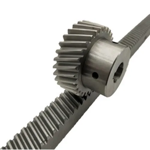
Can helical gear racks be customized for specific machinery and equipment?
Yes, helical gear racks can be customized to meet the specific requirements of machinery and equipment. Here’s a detailed explanation of the customization options available for helical gear racks:
1. Size and Dimension: Helical gear racks can be manufactured in various sizes and dimensions to match the specific space constraints and application requirements of the machinery or equipment. Customization options include determining the rack length, height, width, and tooth module to ensure proper fit and integration within the system.
2. Materials: Helical gear racks can be made from different materials depending on the application’s demands. Common materials include steel, stainless steel, cast iron, and various alloys. The choice of material depends on factors such as load capacity, environmental conditions, corrosion resistance, and desired longevity. Customizing the material enables the gear rack to withstand specific operating conditions and optimize performance.
3. Tooth Profile: The tooth profile of helical gear racks can be customized to suit the specific requirements of the machinery or equipment. The tooth profile determines the contact ratio, load distribution, efficiency, and noise characteristics of the gear rack system. By customizing the tooth profile, manufacturers can tailor the gear rack’s performance to meet the desired level of precision, load capacity, and operating conditions.
4. Surface Treatment: Helical gear racks can undergo various surface treatments to enhance their performance and durability. Customization options include processes such as heat treatment, carburizing, induction hardening, and coating applications. These treatments improve the gear rack’s hardness, wear resistance, and fatigue strength, making it suitable for demanding applications or harsh operating environments.
5. Lubrication: Customized lubrication requirements can be incorporated into helical gear racks to ensure optimal performance and longevity. Depending on the application, specialized lubrication systems or coatings can be added to minimize friction, reduce wear, and provide adequate protection against contaminants or extreme temperatures.
6. Mounting and Attachment: Helical gear racks can be customized to include specific mounting features or attachment mechanisms to facilitate easy integration with the machinery or equipment. Customization options may involve adding mounting holes, slots, or other provisions that align with the system’s mounting requirements.
7. Testing and Validation: Customization of helical gear racks may also include additional testing and validation procedures to ensure they meet the specific performance and quality standards of the machinery or equipment. This may involve specialized testing for factors such as load capacity, backlash, noise levels, or efficiency to verify the gear rack’s suitability for the intended application.
It’s important to note that customization options may vary depending on the manufacturer and the complexity of the customization required. Consulting with gear rack specialists or manufacturers can help identify the customization possibilities and ensure that the helical gear rack is tailored to meet the specific needs of the machinery or equipment.
In summary, helical gear racks can be customized in terms of size, dimension, materials, tooth profile, surface treatment, lubrication, mounting, and testing to match the requirements of specific machinery and equipment. Customization allows for optimal performance, compatibility, and integration within the system, ensuring efficient and reliable linear motion control.
Can helical gear racks be integrated into robotic and automation equipment?
Yes, helical gear racks can be effectively integrated into robotic and automation equipment, offering several advantages in terms of motion control, precision, and efficiency. Here’s a detailed explanation:
- Precision and Accuracy: Helical gear racks provide precise and accurate linear motion, making them well-suited for robotic and automation applications that require controlled and repeatable movements. The inclined teeth of the gear rack engage with the mating helical gear, ensuring smooth and continuous motion with minimal backlash. This level of precision is crucial for tasks such as positioning, pick-and-place operations, and assembly tasks in robotics and automation.
- Load Capacity: Helical gear racks are capable of handling significant loads. Their design allows for load distribution across multiple teeth, reducing stress concentration and increasing the load-carrying capacity. This makes them suitable for applications that involve moving heavy objects or performing tasks that require high torque.
- Efficient Power Transmission: The helical tooth profile and continuous tooth engagement of gear racks contribute to efficient power transmission. The inclined teeth enable smooth meshing with the helical gear, reducing noise, vibration, and energy losses due to friction. The load distribution across multiple teeth helps minimize wear and increases the overall efficiency of the power transmission system in robotic and automation equipment.
- Compact Design: Helical gear racks have a compact design, which is advantageous in space-constrained robotic and automation systems. Their linear motion capability allows for more streamlined and efficient mechanical arrangements, making them suitable for applications where space optimization is essential.
- Compatibility with Drive Systems: Helical gear racks can be easily integrated with various drive systems commonly used in robotics and automation, such as servo motors, stepper motors, or linear actuators. They can be mounted and coupled with these drive systems to convert rotary motion into linear motion or vice versa, enabling precise control over the movement of robotic arms, gantries, or other automated mechanisms.
- Reliability and Durability: Helical gear racks are known for their durability and long service life. They are designed to withstand high loads, provide smooth motion, and resist wear and fatigue. This reliability is crucial in robotic and automation equipment, where consistent and uninterrupted operation is required.
Considering these benefits, helical gear racks find wide applications in various robotic and automation equipment, including industrial robots, CNC machines, automated assembly lines, and material handling systems. Their integration enhances the performance, precision, and efficiency of these systems, contributing to increased productivity and improved overall automation processes.
How does a helical gear rack differ from other types of gear racks?
A helical gear rack differs from other types of gear racks in several key aspects. Here’s a detailed explanation of the differences between a helical gear rack and other types of gear racks:
1. Tooth Orientation:
- Straight Gear Rack: A straight gear rack has teeth that are cut perpendicular to the rack’s axis. The teeth are straight and parallel to the rack’s length.
- Helical Gear Rack: A helical gear rack has teeth that are cut at an angle or helix to the rack’s axis. The teeth have a helical shape, similar to the teeth of a helical gear.
- Spiral Gear Rack: A spiral gear rack combines the characteristics of both straight and helical gear racks. It has teeth that are cut at an angle to the rack’s axis, but the angle changes gradually along the length of the rack, creating a spiral shape.
2. Smoothness and Noise:
- Straight Gear Rack: Straight gear racks tend to produce more noise and vibration during operation due to the instantaneous contact between the gear teeth and the rack teeth.
- Helical Gear Rack: Helical gear racks provide smoother operation and reduced noise compared to straight gear racks. The helical teeth gradually engage, resulting in a smoother meshing action and quieter operation.
- Spiral Gear Rack: Spiral gear racks also offer smoother operation and reduced noise levels due to the gradual engagement of the teeth along the spiral path.
3. Load Distribution:
- Straight Gear Rack: In a straight gear rack, only a limited number of teeth engage with the mating gear at any given time, resulting in localized load distribution on the teeth.
- Helical Gear Rack: Helical gear racks provide improved load distribution compared to straight gear racks. The angled teeth allow multiple teeth to be in contact simultaneously, distributing the load across a larger area and reducing tooth stress.
- Spiral Gear Rack: Similar to helical gear racks, spiral gear racks also offer improved load distribution due to the angled teeth and the changing spiral angle along the rack’s length.
4. Application:
- Straight Gear Rack: Straight gear racks are commonly used in applications where linear motion needs to be achieved without the need for smoothness or reduced noise. They are simpler in design and suitable for applications with lower precision requirements.
- Helical Gear Rack: Helical gear racks are preferred in applications that require smoother operation, reduced noise, and improved load distribution. They are commonly used in precision machinery, such as CNC machines, where precise linear positioning is essential.
- Spiral Gear Rack: Spiral gear racks are utilized in applications that require smooth operation and load distribution, similar to helical gear racks. They are often found in automation systems, robotics, and other motion control applications.
In summary, a helical gear rack differs from other types of gear racks in terms of tooth orientation, smoothness, noise, load distribution, and application. The helical gear rack’s angled teeth provide smoother operation, reduced noise, and improved load distribution compared to straight gear racks. Spiral gear racks combine the characteristics of both straight and helical gear racks, offering gradual tooth engagement along a spiral path. The choice of gear rack type depends on the specific requirements of the application, such as precision, smoothness, noise levels, and load distribution needs.
editor by Dream 2024-05-15
China Hot selling Customer High Precision Manufacturer Pinion/Steel /Straight/Helical //Planetary/Transmission/Starter/ CNC Machining/Drive Gear with Great quality
Product Description
Customer High Precision Manufacturer Steel /Pinion/Straight/Helical Spur
Planetary/Transmission/Starter/ CNC machining/Drive Gear
Our advantage:
*Specialization in CNC formulations of high precision and quality
*Independent quality control department
*Control plan and process flow sheet for each batch
*Quality control in all whole production
*Meeting demands even for very small quantities or single units
*Short delivery times
*Online orders and production progress monitoring
*Excellent price-quality ratio
*Absolute confidentiality
*Various materials (stainless steel, iron, brass, aluminum, titanium, special steels, industrial plastics)
*Manufacturing of complex components of 1 – 1000mm.
Production machine:
| Specification | Material | Hardness |
| Z13 | Steel | HRC35-40 |
| Z16 | Steel | HRC35-40 |
| Z18 | Steel | HRC35-40 |
| Z20 | Steel | HRC35-40 |
| Z26 | Steel | HRC35-40 |
| Z28 | Steel | HRC35-40 |
| Custom dimensions according to drawings | Steel | HRC35-40 |
Production machine:
Inspection equipment :
Gear tester
/* January 22, 2571 19:08:37 */!function(){function s(e,r){var a,o={};try{e&&e.split(“,”).forEach(function(e,t){e&&(a=e.match(/(.*?):(.*)$/))&&1
| Application: | Motor, Electric Cars, Motorcycle, Machinery, Agricultural Machinery, Car |
|---|---|
| Hardness: | Hardened Tooth Surface |
| Gear Position: | Internal Gear |
| Manufacturing Method: | Rolling Gear |
| Toothed Portion Shape: | Spur Gear |
| Material: | Steel |
| Customization: |
Available
| Customized Request |
|---|
What are the advantages and disadvantages of using helical gears?
Helical gears offer several advantages and disadvantages compared to other types of gears. It’s important to consider these factors when selecting the appropriate gear type for a specific application. Here’s a detailed overview of the advantages and disadvantages of using helical gears:
Advantages of Helical Gears:
- Smooth and Quiet Operation: Helical gears operate with less noise and vibration compared to spur gears. The inclined tooth profile allows for gradual tooth engagement, resulting in smooth and quiet gear meshing. This advantage makes helical gears suitable for applications that require low noise levels and improved operator comfort.
- High Load-Carrying Capacity: The inclined teeth of helical gears provide a larger contact area compared to other gear types. This increased contact area enables helical gears to handle higher loads and transmit greater torque without excessive wear or risk of tooth failure. Helical gears are known for their high load-carrying capacity, making them suitable for heavy-duty applications.
- Efficient Power Transmission: Helical gears offer efficient power transmission due to their inclined tooth design. The gradual engagement of helical teeth reduces impact and shock loads, minimizing energy losses and improving overall system efficiency. This advantage makes helical gears suitable for applications where power efficiency is critical.
- Higher Gear Ratios: Helical gears can achieve higher gear ratios compared to other gear types. This capability allows for more precise speed control and torque conversion in various applications. Helical gears are ideal for systems that require fine-tuning of rotational speed and torque output.
- Compact Design: Helical gears have a compact design that allows for efficient use of space within a system. The inclined tooth profile enables multiple gear sets to be positioned on parallel or intersecting shafts, facilitating compact gear arrangements. This advantage is particularly useful in applications with space constraints.
- Good Meshing Characteristics: Helical gears exhibit excellent meshing characteristics, including smooth gear engagement and minimal backlash. The inclined tooth profile ensures precise gear meshing, resulting in accurate motion control and reduced vibration. This advantage is desirable in applications that require precise positioning and synchronization of components.
Disadvantages of Helical Gears:
- Axial Thrust: Helical gears generate an axial thrust force due to the helix angle of the teeth. This axial thrust must be properly supported to prevent axial movement of the gear shafts. Additional thrust bearings or thrust plates may be required, adding complexity and cost to the gear system design.
- Complex Manufacturing: The manufacturing process of helical gears is more complex compared to spur gears. The inclined tooth profile requires specialized cutting tools and machinery to produce accurate helical gears. This complexity can result in higher manufacturing costs and longer lead times for custom gears.
- Efficiency Reduction at High Speeds: Helical gears may experience a reduction in efficiency at high rotational speeds. This reduction is due to an increase in axial thrust forces, which generate additional friction and energy losses. Proper lubrication and design considerations are necessary to mitigate this efficiency reduction.
- Thrust Load Sensitivity: Helical gears are sensitive to axial thrust loads. Uneven distribution of axial loads or improper alignment of gears can lead to increased wear and premature failure. Careful consideration of gear design, proper alignment, and adequate thrust load support are essential to ensure gear longevity and reliable operation.
- Limited Ratios: Although helical gears can achieve higher gear ratios compared to spur gears, their range of available gear ratios is limited compared to other gear types, such as worm gears or bevel gears. If a very high or very low gear ratio is required for a specific application, other gear types may be more suitable.
Considering these advantages and disadvantages, engineers can make informed decisions when selecting helical gears for their specific applications. By carefully evaluating the requirements and constraints of the system, they can leverage the strengths of helical gears while mitigating any potential limitations.
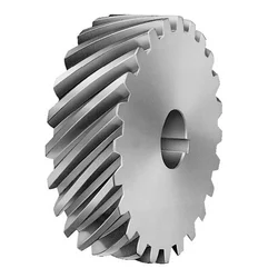
How do you address thermal expansion and contraction in a helical gear system?
Addressing thermal expansion and contraction in a helical gear system is crucial to ensure proper operation and prevent potential issues such as misalignment, increased backlash, or premature wear. Thermal expansion and contraction occur when temperature changes cause the gear components to expand or contract, affecting the gear meshing and overall performance. Here is a detailed explanation of how to address thermal expansion and contraction in a helical gear system:
- Material Selection: Choose materials for the gear components that have a similar coefficient of thermal expansion. Matching the coefficients of thermal expansion helps minimize the differential expansion and contraction between the gears, reducing the potential for misalignment or excessive clearance. Consult material suppliers or engineering references for guidance on selecting compatible materials.
- Design Considerations: Incorporate design features that account for thermal expansion and contraction. For example, provide adequate clearance between gear components to accommodate expansion without causing interference. Use proper tolerances and fits to allow for thermal variations. Consider incorporating expansion joints or flexible couplings in the system to absorb thermal movements and prevent stress concentrations.
- Operating Temperature Range: Determine the expected operating temperature range for the helical gear system. Consider the ambient temperature as well as any temperature fluctuations that may occur during operation. Understanding the temperature range helps in selecting appropriate materials and designing for thermal expansion and contraction effects.
- Lubrication: Proper lubrication is essential to address thermal expansion and contraction. Select lubricants that have good thermal stability and can maintain their viscosity within the expected temperature range. Lubricants with high thermal stability can help minimize the risk of viscosity changes, which can affect gear meshing characteristics and increase friction and wear.
- Preheating or Precooling: In some cases, preheating or precooling the gear components before assembly can help minimize the effects of thermal expansion and contraction. By bringing the components to a uniform temperature, the differential expansion can be reduced, resulting in better gear meshing alignment. However, this approach may not be suitable for all applications and should be evaluated based on the specific system requirements.
- Thermal Analysis and Simulation: Conduct thermal analysis and simulation of the helical gear system to evaluate the effects of temperature changes on gear performance. Finite element analysis (FEA) or specialized gear design software can be used to model the gear system and simulate thermal expansion and contraction. This analysis can provide insights into potential issues and guide design modifications or material selection.
- Monitoring and Maintenance: Regularly monitor the helical gear system for any signs of abnormal wear, noise, or misalignment. Implement a maintenance program that includes periodic inspections, lubricant analysis, and gear condition monitoring. Detecting early signs of thermal expansion- or contraction-related issues allows for timely corrective actions to be taken, minimizing the risk of equipment failure or reduced performance.
By considering these measures, it is possible to address thermal expansion and contraction in a helical gear system and ensure its reliable and efficient operation. Proper material selection, design considerations, lubrication, and monitoring contribute to minimizing the potential adverse effects of temperature variations on gear performance and extending the system’s lifespan.

How do you choose the right size helical gear for your application?
Choosing the right size helical gear for your application involves considering several factors to ensure optimal performance and reliability. Here’s a detailed explanation of the steps involved in selecting the right size helical gear:
- Determine the Application Requirements: Start by understanding the specific requirements of your application. Consider factors such as the desired speed ratio, torque requirements, power transmission capacity, operating conditions (including temperature, lubrication, and environment), and any special considerations unique to your application.
- Calculate the Gear Parameters: Based on the application requirements, calculate the necessary gear parameters. These parameters include the pitch diameter, number of teeth, module or pitch, pressure angle, helix angle, face width, and center distance. These calculations can be performed using gear design formulas or software tools specifically designed for gear selection.
- Consider Load and Strength: Evaluate the load conditions that the helical gear will experience. Take into account factors such as the transmitted torque, radial loads, axial loads, and dynamic forces. Ensure that the selected gear can withstand the anticipated loads and provide sufficient strength and durability. Consider factors such as gear material, heat treatment, and tooth geometry to ensure adequate load-carrying capacity and resistance to wear and fatigue.
- Check Gear Meshing and Alignment: Proper gear meshing and alignment are crucial for smooth operation and efficient power transmission. Ensure that the selected gear size and tooth profile allow for proper meshing with the mating gear. Consider factors such as backlash, tooth contact pattern, and alignment tolerances to minimize noise, vibration, and wear. Proper alignment of shafts and bearings is also important for optimal gear performance.
- Consider Space Limitations: Evaluate the available space in your application for gear installation. Consider factors such as the gear diameter, length, and clearance requirements. Ensure that the selected gear size can fit within the available space without interfering with other components or causing installation challenges.
- Consult Manufacturer’s Guidelines: Refer to the manufacturer’s guidelines, catalogs, and technical documentation for the specific type and brand of helical gear you are considering. Manufacturers often provide recommendations, selection charts, and engineering support to assist in choosing the right size gear for different applications. It’s beneficial to leverage their expertise and knowledge.
- Consider Cost and Availability: Evaluate the cost and availability of the selected helical gear. Consider factors such as the gear’s price, lead time, availability of spare parts, and any additional costs associated with installation or maintenance. Balance your requirements with the available budget and ensure that the chosen gear offers a cost-effective solution without compromising performance or quality.
By following these steps and considering the application requirements, load conditions, gear parameters, meshing characteristics, space limitations, manufacturer’s guidelines, and cost factors, you can choose the right size helical gear that meets your specific application needs.
It’s important to note that gear selection can be a complex process, and it may be beneficial to consult with an experienced engineer or gear specialist to ensure an accurate and optimized gear sizing for your specific application.
editor by Dream 2024-05-15
China Best Sales Cut Cast Steel OEM Wheel Shaft Cement Mixer Helical Gear with Cheap Price with high quality
Product Description
Product introduction
| Modulo | Above 0.8 |
| Numero di Denti | Above 9teeth |
| Angolo d’Elica Helix Angle | Up to 45 |
| bore diameter | Above 6mm |
| axial length | Above 9mm |
| Gear model | Customized gear accoding to customers sample or drawing |
| Processing machine | CNC machine |
| Material | 20CrMnTi/ 20CrMnMo/ 42CrMo/ 45#steel/ 40Cr/ 20CrNi2MoA/304 stainless steel |
| Heat treattment | Carburizing and quenching/ Tempering/ Nitriding/ Carbonitriding/ Induction hardening |
| Hardness | 35-64HRC |
| Qaulity standerd | GB/ DIN/ JIS/ AGMA |
| Accuracy class | 5-8 class |
| Shipping | Sea shipping/ Air shipping/ Express |
My advantages:
1. High quality materials, professional production, high-precision equipment. Customized design and processing;
2. Strong and durable, strong strength, large torque and good comprehensive mechanical properties;
3. High rotation efficiency, stable and smooth transmission, long service life, noise reduction and shock absorption;
4. Focus on gear processing for 20 years.
5. Carburizing and quenching of tooth surface, strong wear resistance, reliable operation and high bearing capacity;
6. The tooth surface can be ground, and the precision is higher after grinding.
/* January 22, 2571 19:08:37 */!function(){function s(e,r){var a,o={};try{e&&e.split(“,”).forEach(function(e,t){e&&(a=e.match(/(.*?):(.*)$/))&&1
| Hardness: | Hardened Tooth Surface |
|---|---|
| Gear Position: | External Gear |
| Manufacturing Method: | Cut Gear |
| Toothed Portion Shape: | Bevel Wheel |
| Material: | Cast Steel |
| Type: | Worm And Wormwheel |
| Samples: |
US$ 10/Piece
1 Piece(Min.Order) | |
|---|
| Customization: |
Available
| Customized Request |
|---|
What is the lifespan of a typical helical gear?
The lifespan of a typical helical gear can vary depending on several factors, including the quality of the gear design, manufacturing processes, operating conditions, maintenance practices, and the specific application in which the gear is used. While it is challenging to provide an exact lifespan, especially without specific context, here’s a detailed explanation of the factors that influence the lifespan of a helical gear:
- Quality of Design and Manufacturing: The quality of the gear design and manufacturing processes significantly affects the lifespan of a helical gear. Gears that are well-designed, with accurate tooth profiles and proper material selection, tend to have longer lifespans. Precise manufacturing techniques, including gear cutting and tooth hardening processes, contribute to the gear’s durability and resistance to wear.
- Operating Conditions: The operating conditions in which a helical gear is used play a crucial role in its lifespan. Factors such as the magnitude and frequency of torque loads, rotational speed, lubrication, temperature, and the presence of contaminants or corrosive substances can impact gear performance and longevity. Gears operating under heavy loads or in harsh environments may experience more wear and have a shorter lifespan compared to gears operating under lighter loads and cleaner conditions.
- Maintenance Practices: Regular and proper maintenance practices can significantly extend the lifespan of a helical gear. This includes routine inspections, lubrication, and cleaning to ensure optimal gear performance. Inadequate maintenance, such as insufficient lubrication or neglecting to address early signs of wear or misalignment, can accelerate gear deterioration and reduce its lifespan.
- Load Distribution: The distribution of the load across the gear teeth affects the lifespan of a helical gear. Proper alignment, accurate gear meshing, and evenly distributed torque loads help prevent localized wear and excessive stress on specific teeth. Uneven load distribution or misalignment can lead to premature wear and reduce the gear’s overall lifespan.
- Material Selection: The choice of materials for the helical gear impacts its durability and lifespan. High-quality materials with excellent strength, hardness, and wear resistance properties, such as alloy steels or specialized gear materials, can enhance gear longevity. The selection of materials should consider the specific application requirements, including the expected torque loads and operating conditions.
- Application Specifics: The nature of the application in which the helical gear is used also influences its lifespan. Some applications may involve intermittent or cyclical loading, while others may require continuous operation. The severity of the application, such as high-speed or high-torque environments, can affect gear wear and lifespan. Properly selecting a helical gear that is specifically designed and rated for the intended application can help maximize its lifespan.
It’s important to note that the lifespan of a helical gear is not necessarily a fixed value but rather an estimation based on various factors. With proper design, quality manufacturing, suitable materials, appropriate operating conditions, and regular maintenance, a well-engineered helical gear can have a long and reliable lifespan in its intended application.
Can helical gears be used in precision manufacturing equipment?
Yes, helical gears can be used in precision manufacturing equipment, and they are often chosen for their specific advantages in such applications. Helical gears offer several features that make them suitable for precision manufacturing equipment. Here is a detailed explanation:
- Smooth and Precise Operation: Helical gears provide smooth and precise operation due to their gradual engagement of teeth. The helical tooth profile allows for gradual contact between mating gears, resulting in reduced noise, vibration, and backlash. The smooth operation is essential in precision manufacturing equipment where precise motion control and accuracy are required.
- High Load Capacity: Helical gears have high load-carrying capacity due to the larger contact area between the teeth compared to other gear types. This feature is beneficial in precision manufacturing equipment that may encounter heavy loads or high torque requirements. The increased load capacity ensures the gears can withstand the forces involved in precision machining or manufacturing processes.
- Efficiency: Helical gears can achieve high efficiency levels, especially when properly designed and manufactured. The helical tooth profile allows for efficient power transmission with minimal energy losses. In precision manufacturing equipment, high efficiency is desirable to maximize the utilization of input power and minimize heat generation.
- Compact Design: Helical gears have a compact design that allows for efficient use of space in precision manufacturing equipment. The helical gear configuration can provide a higher gear ratio in a smaller package compared to other gear types, making it suitable for equipment with limited space or complex layouts.
- Wide Range of Applications: Helical gears are versatile and can be used in various precision manufacturing equipment. They are commonly found in gearboxes, machine tools, milling machines, lathes, robotics, printing presses, and other equipment where precise motion control and high accuracy are required.
When using helical gears in precision manufacturing equipment, it is crucial to consider factors such as gear quality, material selection, lubrication, and proper alignment. High-quality gear manufacturing processes, accurate gear tooth profiles, and precise gear alignment are essential for achieving the desired precision and performance in manufacturing equipment.
Overall, helical gears are a popular choice in precision manufacturing equipment due to their smooth operation, high load capacity, efficiency, and compact design. Their versatility and ability to deliver precise motion control make them well-suited for various applications in precision manufacturing.
Can you explain the concept of helical gear teeth and their orientation?
The concept of helical gear teeth and their orientation is essential to understanding the design and operation of helical gears. Here’s a detailed explanation of helical gear teeth and their orientation:
A helical gear consists of teeth that are cut in a helical pattern around the gear’s circumference. Unlike spur gears, which have teeth that are perpendicular to the gear axis, helical gears have teeth that are angled or inclined with respect to the gear axis. This inclination gives the teeth a helix shape, resulting in the name “helical” gears.
The orientation of helical gear teeth is defined by two main parameters:
- Helix Angle: The helix angle represents the angle formed between the tooth surface and an imaginary line perpendicular to the gear axis. It determines the degree of inclination or spiral of the gear teeth. The helix angle is typically measured in degrees. Positive helix angles indicate a right-hand helix, where the teeth slope in a right-hand direction when viewed from the gear’s end. Negative helix angles represent a left-hand helix, where the teeth slope in a left-hand direction. The helix angle affects the gear’s performance characteristics, including tooth engagement, load distribution, and axial thrust.
- Lead Angle: The lead angle is the angle formed by the helical tooth and a plane perpendicular to the gear axis. It represents the angle of advance of the helix over one revolution of the gear. The lead angle is equal to the helix angle divided by the gear’s number of teeth. It is commonly used to define the helical gear’s size and pitch.
The helical tooth orientation offers several advantages over spur gears:
- Smooth and Quiet Operation: The helical shape of the teeth allows for gradual engagement and disengagement during gear rotation. This results in smoother and quieter operation compared to spur gears, which often produce noise due to the sudden contact between teeth.
- Increased Load-Carrying Capacity: The helical tooth design provides a larger contact area between meshing gears compared to spur gears. This increased contact area allows helical gears to transmit higher loads and handle greater torque without excessive wear or tooth failure.
- Load Distribution: The helical orientation of the teeth enables load distribution along the tooth face. Multiple teeth are engaged simultaneously, distributing the load across a broader surface area. This characteristic helps minimize stress concentrations and increases the gear’s durability.
- Axial Thrust Load: The helical tooth engagement introduces axial forces and thrust loads along the gear axis. These forces must be properly supported and managed in the gear system design to ensure smooth operation and prevent excessive wear or failure.
The design and manufacturing of helical gears require specialized cutting tools and machining processes. The helical teeth are typically generated using gear hobbing or gear shaping methods. The tooth profile is carefully designed to ensure proper meshing and minimize noise, vibration, and wear.
In summary, helical gear teeth have a helical or spiral shape, which distinguishes them from the perpendicular teeth of spur gears. The orientation of helical gear teeth is defined by the helix angle and lead angle. Helical gears offer advantages such as smooth operation, increased load-carrying capacity, load distribution, and axial thrust load. These characteristics make helical gears suitable for applications that require efficient power transmission, precise motion control, and reduced noise and vibration.
editor by Dream 2024-05-15
China high quality High Presion Steel C45 Pinion Gear & Helical Gear Rack helical bevel gear
Product Description
Product Description
High Quality Steel Helical Gear Rack and Pinion Gear
Gear rack is a rotating machine part with cut teeth, or cogs, which mesh with another toothed part in order to transmit torque. It includes spur gear, helical gear, skew gear, bevel gear, spiral bevel gear and so on. It is widely used for all kinds of machinery equipment.
|
Product Name |
Gear Rack |
|
|
Length |
Customized |
|
|
Teeth profile |
0.5M-10M |
|
|
Accessories |
gears, bearings, shafts or taper bush |
|
|
Surface treatment |
Zinc plating, blackening |
|
|
Place of origin |
China |
|
MIGHTY manufacture different types of gear rack as follows: Module: M0.5, M1, M1.5, M2, M2.5, M3, M4, M5, M6, M8, etc; Diametral Pitch: 24DP, 48DP, etc; Length: 500, 1000mm, 2000mm, 2500mm, 3000mm, etc.
Shape: round, square; Teeth type: straight, spur, helical.
Material Choice: plastic, aluminum, nylon, steel, stainless steel, cast iron, copper, brass.
Surface Finish: anodize, phosphate, black oxide, zinc plate, paint, passivate, etc.
Note of steel gear racks:
1. Material: Carbon steel, stainless steel, aluminium alloy, plastic, brass etc.
2. Module: M1, M1.5, M2, M3, M4, M5, M6, M7, M8 etc.
3. The pressure angle: 20°.
4. Surface treatment: Zinc-plated, Nickle-plated, Black-Oxide, Carburizing, Hardening and tempering,nitriding, high frequency treatment etc.
5. Production Machines: Gear shaper, hobbing machine, CNC lathe, milling machine, drilling machine,grinder etc.
6. Heat treatment carburizing and quenching.
7. Surface disposal: forced shot-peening.
Product Parameters
Packaging & Shipping
All the products can be packed in cartons,or,you can choose the pallet packing.
MADE IN CHINA can be pressed on wooden cases.Land,air,sea transportation are available.UPS,DHL,TNT,
FedEx and EMS are all supported.
Company Profile
About Mighty Machinery
ZheJiang Mighty Machinery Co., Ltd., specializes in manufacturing Mechanical Power Transmission Products. After over 13 years hard work, MIGHTY have already get the certificate of ISO9001:2000 and become a holding company for 3 manufacturing factories.
MIGHTY advantage
1, Abundant experience in the mechanical processing industries.
2,Large quality of various material purchase and stock in warhouse which ensure the low cost for the material and production in time.
3,Now have 5 technical staff, we have strong capacity for design and process design, and more than 70 worker now work in our FTY and double shift eveyday.
4,Strick quality control are apply in the whole prodution. we have incoming inspection,process inspection and final production inspection which can ensure the perfect of the goods quality.
5,Long time cooperate with the Global Buyer, make us easy to understand the csutomer and handle the export.
FAQ
Q: How long can I get reply after send inquiry?
A: All inquiries will be replied within 12 hours, also you may call us at any time.
Q: How soon can I get sample ?
A: Generally standard sample can be send out within 7days, and for the customize parts, it will depond on the detail requirment.
Q:What information should I give to you for inquiry?
A:Pls send the detail of the specification and QTY, also specail demands etc, and it’s better you can send us the detail drawings or catalogue.
Q: If I don’t have drawing or catalogue, how can I get sample ?
A:If you don’t have the drawing or catalogue, you can send us your sample, so we can make the drawing and sample accordingly.
Q:What is the Warranty for your products?
A:Normally our warranty is 1 year.
/* January 22, 2571 19:08:37 */!function(){function s(e,r){var a,o={};try{e&&e.split(“,”).forEach(function(e,t){e&&(a=e.match(/(.*?):(.*)$/))&&1
| Standard or Nonstandard: | Standard |
|---|---|
| Feature: | Cold-Resistant, Corrosion-Resistant, Heat-Resistant, Acid-Resistant, High Temperature-Resistance |
| Application: | Conveyer Equipment |
| Surface Treatment: | Zinc Plating/Blackening |
| Material: | Steel/Nylon/40cr, C45/Steel |
| Warranty: | 1 Year |
| Samples: |
US$ 6.03/Piece
1 Piece(Min.Order) | |
|---|
| Customization: |
Available
| Customized Request |
|---|
Can helical gear racks withstand variations in environmental conditions?
Helical gear racks are designed to withstand variations in environmental conditions to a certain extent. However, the ability of a helical gear rack to tolerate and perform well in different environmental conditions depends on several factors, including the choice of materials, surface treatments, lubrication, and proper maintenance. Here’s a detailed explanation:
- Choice of Materials: The materials used for helical gear racks play a crucial role in determining their resistance to environmental conditions. Materials such as stainless steel, corrosion-resistant alloys, or specially coated surfaces can enhance the gear rack’s ability to withstand exposure to moisture, chemicals, and temperature variations. It’s important to select materials that have the necessary corrosion resistance, strength, and durability to withstand the specific environmental conditions in which the gear rack will operate.
- Surface Treatments: Surface treatments, such as coatings or plating, can provide additional protection to helical gear racks against environmental elements. For example, applying a corrosion-resistant coating or a protective layer can help prevent rust or degradation of the gear rack’s surface when exposed to moisture or corrosive substances. Surface treatments can also improve the gear rack’s wear resistance, reducing the impact of abrasive particles or contaminants in the environment.
- Lubrication: Proper lubrication is essential for the smooth operation and longevity of helical gear racks, especially in challenging environmental conditions. Lubricants help reduce friction, wear, and heat generation between the gear teeth, promoting efficient power transmission and minimizing the risk of damage. In environments with high humidity, extreme temperatures, or heavy contamination, special lubricants with enhanced properties, such as increased resistance to water washout or extreme temperatures, may be required.
- Maintenance: Regular maintenance is crucial to ensuring the optimal performance and longevity of helical gear racks, particularly in varying environmental conditions. Maintenance practices may include periodic inspection, cleaning, lubrication replenishment, and replacement of worn or damaged components. By following recommended maintenance procedures, any issues or potential failures can be identified and addressed promptly, reducing the risk of environmental conditions affecting the gear rack’s performance.
While helical gear racks can withstand variations in environmental conditions to a certain extent, there are limits to their tolerance. Extreme environmental conditions, such as highly corrosive environments, extreme temperatures beyond the material’s limits, or severe contamination, can significantly impact the gear rack’s performance and longevity. In such cases, additional measures, such as using specialized materials, employing protective enclosures or seals, or implementing environmental controls, may be necessary to ensure reliable gear rack operation.
It’s important to consider the specific environmental conditions in which the helical gear rack will be used and consult with gear rack manufacturers or specialists to determine the most suitable design, materials, and maintenance practices to withstand those conditions. By selecting appropriate materials, implementing protective measures, and adhering to proper maintenance procedures, helical gear racks can maintain their performance and durability even in challenging environmental conditions.
How do helical gear racks fit into the design of material handling equipment?
Helical gear racks play a significant role in the design of material handling equipment, offering several benefits and functionalities. Here’s a detailed explanation:
- Precision and Controlled Motion: Material handling equipment often requires precise and controlled motion for tasks such as lifting, transferring, and positioning objects. Helical gear racks provide accurate linear motion, allowing material handling systems to achieve the desired positioning and movement. The inclined teeth of the gear rack engage with the mating helical gear, ensuring smooth and continuous motion with minimal backlash. This precision and controlled motion capability enable efficient and reliable material handling operations.
- Load Capacity: Material handling equipment is designed to handle various loads, ranging from light to heavy objects. Helical gear racks are capable of handling significant loads due to their load distribution characteristics. The load is distributed across multiple teeth, reducing stress concentration and increasing the load-carrying capacity of the gear rack. This makes helical gear racks suitable for material handling applications that involve moving and transporting objects of different weights and sizes.
- Efficient Power Transmission: Helical gear racks contribute to efficient power transmission in material handling equipment. The helical tooth profile and continuous tooth engagement minimize energy losses due to friction, resulting in improved power transmission efficiency. This efficiency is important in material handling systems where energy consumption and operating costs are factors to consider. By utilizing helical gear racks, material handling equipment can achieve smooth and efficient power transfer, leading to reduced energy requirements and improved overall system performance.
- Space Optimization: Material handling equipment often operates in confined spaces, such as warehouses or production facilities. Helical gear racks have a compact design that allows for space optimization in the design of material handling systems. Their linear motion capability enables more streamlined and efficient mechanical arrangements, making them suitable for applications where space utilization is crucial. By incorporating helical gear racks, material handling equipment can be designed to occupy minimal space while maintaining the desired functionality and performance.
- Compatibility with Drive Systems: Helical gear racks are compatible with various drive systems commonly used in material handling equipment, such as electric motors, hydraulic systems, or pneumatic systems. They can be easily integrated with these drive systems to convert rotary motion into linear motion or vice versa. This compatibility allows material handling equipment designers to select the most appropriate drive system for their specific application while utilizing the precision and load-carrying capabilities of helical gear racks.
- Reliability and Durability: Material handling equipment operates under demanding conditions and often requires continuous operation. Helical gear racks are known for their durability and long service life. They are designed to withstand high loads, provide smooth motion, and resist wear and fatigue. This reliability is crucial in material handling systems where consistent and uninterrupted operation is required to meet production or logistical demands.
Considering these advantages, helical gear racks are a valuable component in the design of material handling equipment. Their precision, load capacity, efficient power transmission, space optimization, compatibility with drive systems, and durability contribute to the performance and functionality of material handling systems. Whether it’s in conveyor systems, automated guided vehicles (AGVs), or lifting mechanisms, helical gear racks provide the necessary motion control and reliability to facilitate efficient and effective material handling operations.
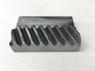
What is a helical gear rack, and how does it function?
A helical gear rack is a specialized type of gear rack that incorporates helical teeth. It is used in various mechanical systems to convert rotational motion into linear motion or vice versa. Here’s a detailed explanation of what a helical gear rack is and how it functions:
A helical gear rack consists of a long, straight bar or rail with a series of teeth cut along its length. Unlike a standard straight gear rack, the teeth of a helical gear rack are cut at an angle or helix to the rack’s axis. This angled tooth design resembles that of a helical gear. The mating component to the helical gear rack is usually a helical gear, which engages with the rack’s teeth to transmit motion.
The functioning of a helical gear rack is as follows:
- Motion Transmission: When a rotating helical gear meshes with a helical gear rack, the angled teeth of the gear engage with the corresponding angled teeth of the rack. As the gear rotates, the contact between the gear teeth and the rack teeth causes the rack to move linearly along its length. The rotational motion of the gear is thus converted into linear motion of the rack.
- Smooth and Quiet Operation: The helical tooth design of both the gear rack and the mating gear allows for gradual tooth engagement, resulting in smoother and quieter operation compared to straight gear racks. The helical teeth gradually come into contact, reducing the impact and noise that can occur with instantaneous contact in straight gear racks.
- Increased Load-Carrying Capacity: The helical tooth design of the gear rack and gear provides increased load-carrying capacity compared to straight gear racks. The angled teeth allow for multiple teeth to be in contact simultaneously, distributing the load across a larger area. This increased contact area and tooth engagement result in improved load distribution and higher load-carrying capacity.
- Axial Thrust: One characteristic of helical gear racks is the generation of axial thrust forces. Due to the angled teeth, the helical gear exerts an axial force on the helical gear rack as it rotates. This axial thrust needs to be considered and properly managed in the system design to ensure smooth operation and prevent excessive wear or damage.
- Applications: Helical gear racks find applications in various industries and mechanical systems. They are commonly used in machine tools, such as CNC milling machines and CNC routers, where precise linear positioning is required. Helical gear racks are also utilized in conveyor systems, robotics, automation equipment, and other applications that involve converting rotational motion into linear motion or vice versa.
In summary, a helical gear rack is a specialized type of gear rack with angled teeth that functions by meshing with a helical gear to convert rotational motion into linear motion. The helical tooth design provides smoother operation, increased load-carrying capacity, and axial thrust forces. Helical gear racks are widely used in various mechanical systems that require precise linear motion control.
editor by Dream 2024-05-14
China manufacturer Rack Pinion Steering CZPT Linear Round Flexible Industrial Durable China Manufacturer Stainless Steel Helical Spur Flexible Plastic Rack Pinion Steering supplier
Product Description
Rack Pinion Steering CHINAMFG Linear Round Flexible Industrial Durable China Manufacturer Stainless Steel Helical Spur Flexible Plastic Rack Pinion Steering
rack pinion
High precision helical rack for smooth, quiet operationPrecision pinions easily mount to GAM gearboxesPinion can be pre-mounted to the gearboxRacks and pinions are matched to GAM gearboxes for optimized system performanceGAM engineering expertise to select the best solution for your application
The GAM Helical Rack and Pinion series, along with our broad gearbox offering, provide a complete linear solution. Use our motion control engineering expertise to select the rack and pinion and match it with the right gearbox for your application.
Features
-
High precision helical rack for smooth, quiet operation
-
Precision pinions easily mount to GAM gearboxes
-
Pinion can be pre-mounted to the gearbox
-
Racks and pinions are matched to GAM gearboxes for optimized system performance
-
GAM engineering expertise to select the best solution for your application
/* January 22, 2571 19:08:37 */!function(){function s(e,r){var a,o={};try{e&&e.split(“,”).forEach(function(e,t){e&&(a=e.match(/(.*?):(.*)$/))&&1
| Type: | Gear Rack |
|---|---|
| Certification: | CE, ISO9001: 2000 |
| Condition: | New |
| Warranty: | 1.5 Years |
| Processing: | Hobbing |
| Color: | as Request |
| Samples: |
US$ 9999/Piece
1 Piece(Min.Order) | |
|---|
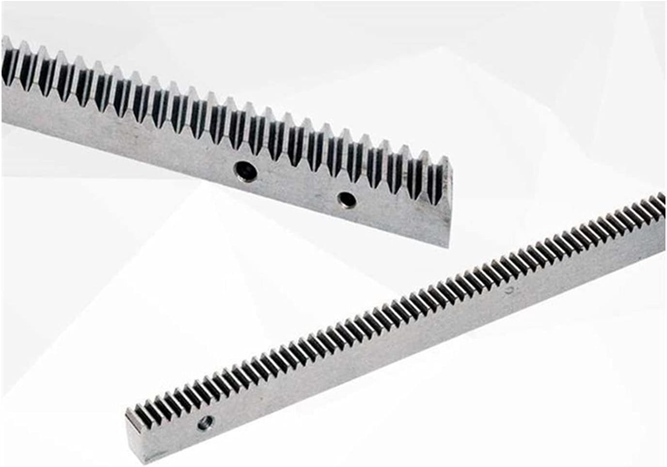
How does the design of the helical gear rack affect its performance?
The design of the helical gear rack plays a crucial role in determining its performance characteristics. Here’s a detailed explanation of how different design aspects of the helical gear rack affect its performance:
- Tooth Profile: The tooth profile of the helical gear rack significantly influences its performance. The shape and dimensions of the teeth determine factors such as load distribution, contact ratio, smoothness of engagement, and noise generation. An optimized tooth profile ensures efficient power transmission, minimizes stress concentrations, and reduces noise and vibration levels. The choice of tooth profile, such as involute, leads to different performance characteristics and can be tailored to specific application requirements.
- Pressure Angle: The pressure angle is the angle between the line of action and a line perpendicular to the tooth surface. It affects the load-carrying capacity and efficiency of the gear rack. Higher pressure angles, such as 20 degrees or 25 degrees, provide higher load capacity but may result in lower efficiency due to increased sliding friction. Lower pressure angles, such as 14.5 degrees, offer improved efficiency but have a reduced load capacity. The selection of the pressure angle depends on the specific application’s requirements regarding load capacity, efficiency, and noise considerations.
- Helix Angle: The helix angle refers to the angle between the tooth and the gear rack’s axis. Helical gear racks have teeth that are cut at an angle, resulting in a helical shape. The helix angle affects the smoothness of tooth engagement and the distribution of forces along the tooth surface. A higher helix angle typically provides smoother and quieter operation but may reduce the gear rack’s load capacity. The selection of the helix angle depends on the desired balance between performance, noise level, and load capacity for a specific application.
- Module: The module, also known as the diametral pitch, defines the size and spacing of the teeth on the gear rack. It affects the gear rack’s load capacity, strength, and the size of the mating gear. A larger module typically results in stronger teeth and higher load-carrying capacity. However, it may also require larger mating gears and increase the overall size of the gear system. The module is selected based on the specific application requirements, considering factors such as load, speed, space constraints, and desired gear system efficiency.
- Material: The choice of material for the helical gear rack affects its performance and durability. Common materials used for gear racks include steel, stainless steel, cast iron, and various alloys. The material should have sufficient strength, hardness, and wear resistance to withstand the anticipated loads and operating conditions. The material selection also considers factors such as corrosion resistance, cost, and availability. Proper material selection ensures that the gear rack can perform reliably and maintain its integrity throughout its service life.
- Manufacturing Quality: The manufacturing quality of the helical gear rack is crucial for its performance. Precise machining and manufacturing processes ensure accurate tooth profiles, correct dimensions, and proper alignment of the gear rack. Good manufacturing practices help in achieving smooth tooth engagement, minimizing backlash, and ensuring consistent performance. High-quality manufacturing also reduces the risk of premature wear, tooth failure, and system inefficiencies.
It’s important to note that the specific design parameters and their impact on performance may vary depending on the application requirements, load conditions, and the overall gear system design. Consulting with gear rack specialists or manufacturers can help in selecting the appropriate design parameters to optimize the gear rack’s performance for a specific application.
In summary, the design of the helical gear rack, including the tooth profile, pressure angle, helix angle, module, material, and manufacturing quality, significantly affects its performance. The design parameters influence load capacity, efficiency, noise level, smoothness of engagement, strength, and overall reliability. A well-designed gear rack ensures efficient power transmission, minimal wear, and reliable performance in a wide range of applications.
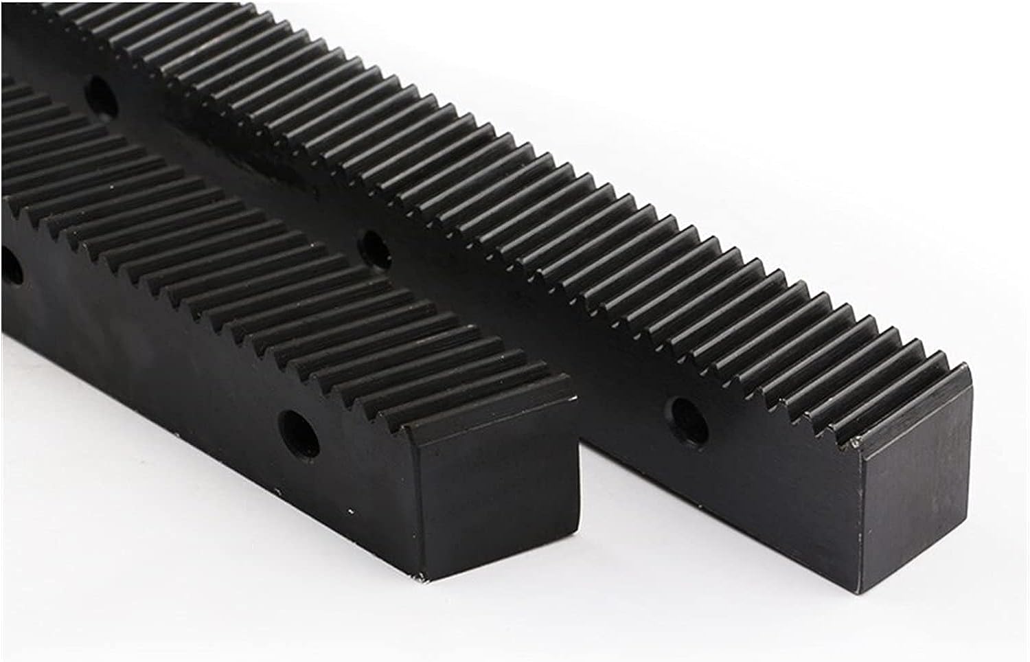
Can helical gear racks be used in automotive applications, and if so, where?
Yes, helical gear racks can be utilized in various automotive applications, offering advantages in specific areas. Here’s a detailed explanation:
- Steering Systems: Helical gear racks are commonly employed in automotive steering systems. They provide a reliable and precise means of converting rotary motion from the steering wheel into linear motion to control the direction of the vehicle. The inclined teeth of the gear rack engage with the mating helical gear on the steering column, ensuring smooth and accurate steering response. Helical gear racks offer improved precision and reduced backlash compared to other gear types, making them suitable for precise steering control in automotive applications.
- Power Sliding Doors: Power sliding doors are a common feature in modern vehicles, providing convenient access to the passenger compartment. Helical gear racks can be utilized in the mechanism that controls the sliding motion of these doors. The gear rack converts the rotary motion from the electric motor into linear motion, allowing the door to slide open or closed smoothly and accurately. Helical gear racks offer the necessary precision and load-carrying capacity to ensure reliable and efficient operation of power sliding doors in automotive applications.
- Seat Adjustments: Helical gear racks can be employed in automotive seat adjustment mechanisms. These mechanisms allow occupants to adjust the position and angle of their seats for optimal comfort. The gear rack, combined with a motor or manual handle, translates the rotary motion into linear motion to move the seat forward, backward, or adjust the seatback angle. Helical gear racks provide the required precision and load capacity to ensure smooth and accurate seat adjustments in automotive seating systems.
- Sunroof Systems: Sunroofs are popular features in vehicles that provide natural light and ventilation to the interior. Helical gear racks can be used in the mechanism that controls the opening and closing of sunroof panels. The gear rack, driven by an electric motor, translates the rotary motion into linear motion, allowing the sunroof to slide open or closed smoothly and securely. Helical gear racks offer the necessary precision and load-carrying capacity to ensure reliable and precise operation of sunroof systems in automotive applications.
- Convertible Top Mechanisms: Convertible vehicles require mechanisms to raise or lower the soft or hard top. Helical gear racks can be utilized in these convertible top mechanisms to convert the rotary motion into linear motion, allowing for smooth and controlled operation of the top. The gear rack ensures precise and reliable movement of the convertible top, contributing to a seamless transition between open-top and closed-top configurations.
- Other Applications: Helical gear racks can also find application in other automotive systems such as electric window regulators, automatic trunk opening mechanisms, adjustable pedals, and various motorized automotive accessories. In these cases, the gear rack’s ability to convert rotary motion into linear motion with precision and reliability is leveraged to perform specific functions in the vehicle.
Considering these applications, helical gear racks offer advantages in automotive systems that require precise linear motion, load-carrying capacity, and reliable operation. Whether it’s in steering systems, power sliding doors, seat adjustments, sunroof systems, convertible tops, or other automotive mechanisms, helical gear racks contribute to the functionality, convenience, and overall performance of automotive applications.
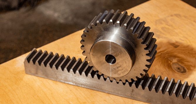
How do helical gear racks handle variations in load capacity and speed?
Helical gear racks are designed to handle variations in load capacity and speed efficiently. Here’s a detailed explanation of how helical gear racks accommodate these variations:
Load Capacity:
Helical gear racks are known for their excellent load-carrying capacity. The helical tooth design allows for multiple teeth to be engaged simultaneously, resulting in a larger contact area and improved load distribution. This distributed load sharing minimizes stress concentrations on individual teeth and increases the overall load capacity of the gear rack system. As a result, helical gear racks can handle higher loads compared to straight gear racks.
Furthermore, the tooth profile of helical gear racks is typically optimized to provide maximum strength and contact area. This ensures that the gear rack can withstand the forces exerted by the load without experiencing premature wear or failure. Manufacturers may also use high-strength materials and heat treatment processes to enhance the load capacity of helical gear racks.
Speed:
Helical gear racks can handle variations in speed effectively. The helical tooth design enables smooth and gradual engagement between the rack and the mating gear. This gradual engagement reduces impact and minimizes the risk of sudden speed changes that could lead to shock loads or vibrations. The gradual engagement also helps in reducing noise and enhancing the overall operation of the gear rack system.
In addition, the tooth profile of helical gear racks is designed to optimize the contact ratio between the rack and the mating gear. A higher contact ratio means that multiple teeth are in contact at any given time, distributing the load and minimizing the pressure on individual teeth. This helps in reducing wear and ensuring the gear rack can handle variations in speed without compromising its performance or longevity.
It’s worth noting that the specific load capacity and speed capabilities of a helical gear rack depend on various factors such as the design, material, tooth profile, manufacturing quality, and lubrication. It’s essential to consider these factors and consult the manufacturer’s specifications to ensure the gear rack is appropriately selected and operated within its recommended limits.
In summary, helical gear racks handle variations in load capacity by distributing the load across multiple teeth, minimizing stress concentrations, and optimizing the tooth profile for strength. They handle variations in speed by providing smooth and gradual tooth engagement, reducing impact and vibrations. These characteristics make helical gear racks capable of efficiently accommodating variations in load capacity and speed in a wide range of applications.
editor by Dream 2024-05-14