Product Description
| 1,Competitive advantage: | |||||
| 1-1, Seasoned Engineering team make your job easy; | |||||
| 1-2, One-Stop service for ODM & OEM product; | |||||
| 1-3, Quick response and professinal English for technology communication; | |||||
| 1-4, Professinal on related parameters of gear analysis to help you get best quality; | |||||
| 1-5, Quality controlling based on ISO9001 and IATF16949; | |||||
| 1-6, Responsibility after-sales service; | |||||
| 1-7, Product assembly capabilities in factory; | |||||
| 1-8, Surface treatment: Powder coating, painting, Plating, Anodize, Electric coating, zinc plating, passivation etc. | |||||
| 2, Parameters | |||||
| Cabinet Parameters | |||||
| Place of Origin: | HangZhou city, ZheJiang , China | Brand | Customization | ||
| Model Number | Gear | Certification | ISO9001, ISO14001, IATF16949 | ||
| Standard | GB/T(China)/AGMA(USA) | Material | SUS: 301/302/304/316; Copper; Aluminum: 6061/6063; Plastic: POM/Nylon or with Fiber. |
||
| Decscription | Greading/Machining/Surface treatment | Part type | Customization Gears with small MOQ | ||
| High precision | 0.02mm | Cycle time | 15 days | ||
| Service: | OEM & ODM included assembly | Technics | CNC, Machining, Stamping etc | ||
| Sample time | 1 weeks | Package | Carton or plywood as requirement | ||
| Drawing format | CAD, Proe, Solidwork, STP, IGS, PDF, AI etc. | HS Code | 84839000 | ||
| 3, Product photos: | |||||
| We are able to support you for metal part developing and production included assembly in our factory. We have our own painting line to make your job easy and best quality for the surface treatment. We are able to support you make precision part without complain from you and your customers. | |||||
/* January 22, 2571 19:08:37 */!function(){function s(e,r){var a,o={};try{e&&e.split(“,”).forEach(function(e,t){e&&(a=e.match(/(.*?):(.*)$/))&&1
| Standard: | GB, EN, API650, China GB Code, JIS Code, TEMA, ASME |
|---|---|
| Tolerance: | +/-0.02mm |
| Surface Treatment: | Powder Coated |
| Machining Method: | CNC Stamping |
| Material: | Stainless Steel |
| Engineer: | Experienced Engineer for Suppoting |
| Customization: |
Available
| Customized Request |
|---|
What safety considerations should be kept in mind when working with helical gear racks?
When working with helical gear racks, it is essential to keep several safety considerations in mind. Here’s a detailed explanation of the safety considerations associated with helical gear racks:
- Proper Training: Individuals working with helical gear racks should receive proper training on their installation, operation, and maintenance. This training should cover safety procedures, potential hazards, and the correct use of personal protective equipment (PPE).
- Pinch Points: Helical gear racks typically have teeth that can create pinch points during operation. It is crucial to exercise caution and avoid placing fingers, hands, or any body part near the gear rack while it is in motion. Adequate guarding or barriers should be in place to prevent accidental contact with moving parts.
- Lubrication: Proper lubrication is essential for the smooth operation and longevity of helical gear racks. However, spilled or excess lubricant can create slippery surfaces, increasing the risk of slips, trips, and falls. Adequate housekeeping measures should be in place to clean up any spills promptly and maintain a safe working environment.
- Overloading and Shock Loads: Helical gear racks have specified load capacities that should not be exceeded. Overloading the gear rack or subjecting it to sudden shock loads can lead to premature wear, tooth failure, or even catastrophic system failure. It is important to adhere to the manufacturer’s recommended load limits and avoid sudden or excessive loading.
- Maintenance and Inspection: Regular maintenance and inspection of helical gear racks are crucial for identifying any signs of wear, damage, or misalignment. Worn or damaged gear racks should be promptly replaced to prevent potential failures. Routine inspections should also include checking for proper lubrication, tightness of fasteners, and overall condition of the gear rack system.
- Electrical Hazards: In applications where helical gear racks are driven by electric motors or other power sources, electrical hazards may be present. Proper electrical safety measures, such as grounding, insulation, and lockout/tagout procedures, should be followed to prevent electrical shocks or accidents.
- Workplace Ergonomics: Consideration should be given to the ergonomics of the work environment to minimize the risk of strain or injury. This may include ensuring proper lighting, clear visibility of the gear rack area, and ergonomic positioning of controls or workstations.
- Personal Protective Equipment (PPE): Depending on the specific workplace hazards associated with helical gear racks, appropriate personal protective equipment (PPE) should be worn. This may include safety glasses, protective gloves, hearing protection, and safety footwear to mitigate the risk of injury.
It is important to consult relevant safety guidelines, regulations, and the manufacturer’s instructions specific to the helical gear rack being used. Following proper safety practices and maintaining a safe working environment helps reduce the risk of accidents, injuries, and equipment damage when working with helical gear racks.
Can helical gear racks be used for both rotary and linear motion?
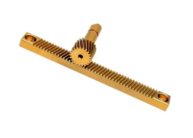
Yes, helical gear racks can be used for both rotary and linear motion applications. They are versatile components that convert rotational motion into linear motion or vice versa, depending on their configuration and usage. Here’s a detailed explanation:
For Rotary-to-Linear Motion:
- When a helical gear engages with a helical gear rack, the rotational motion of the gear is converted into linear motion along the gear rack’s length. As the helical gear rotates, the inclined teeth of the gear mesh with the teeth of the gear rack, causing the rack to move in a linear direction. This linear motion can be used to drive various mechanisms or systems that require linear motion, such as sliding doors, CNC machines, or positioning systems.
- By adjusting the gear ratio and helix angle, the speed and precision of the linear motion can be controlled. Higher gear ratios result in faster linear motion, while smaller helix angles provide smoother engagement and reduce the risk of backlash.
For Linear-to-Rotary Motion:
- Helical gear racks can also be used to convert linear motion into rotary motion. In this configuration, the gear rack is driven by a linear actuator or another mechanism, causing the rack to move linearly. As the rack moves, it engages with a helical gear, which translates the linear motion into rotational motion.
- This setup is commonly used in applications such as rotary indexing tables, where precise and controlled rotary motion is required based on the linear input provided by the gear rack.
It’s important to consider certain factors when using helical gear racks for rotary or linear motion:
- Precision: The precision of the motion depends on the gear rack’s manufacturing quality, gear engagement, and overall system design. Proper alignment, tooth contact, and lubrication are crucial to achieving smooth and accurate motion.
- Load Capacity: The load capacity of a helical gear rack should be considered to ensure it can handle the forces involved in the application. Factors such as the material, tooth profile, and dimensions of the gear rack impact its load-carrying capabilities.
- Backlash: Backlash refers to the clearance or lost motion between the gear teeth when changing direction. Minimizing backlash is important to maintain precision and avoid unwanted play or oscillation in the motion. Proper gear design, high-quality manufacturing, and appropriate adjustments can help reduce backlash.
In summary, helical gear racks can be used for both rotary and linear motion applications. They convert rotational motion into linear motion or vice versa, offering versatility in various mechanical systems. Whether used for rotary-to-linear or linear-to-rotary motion, proper design, alignment, lubrication, and consideration of load capacity and backlash are essential for achieving optimal performance and precision.
What are the primary components and design features of a helical gear rack?
A helical gear rack consists of several primary components and design features that enable its functionality and performance. Here’s a detailed explanation of the primary components and design features of a helical gear rack:
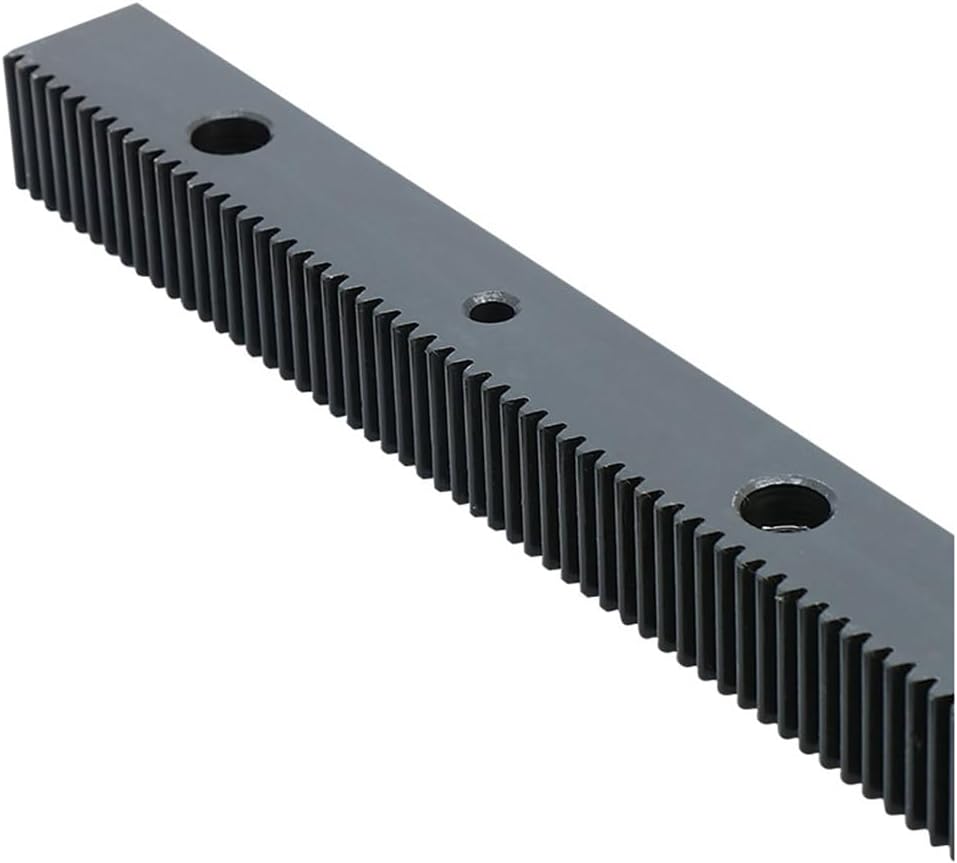
1. Rack Body:
The rack body is the main component of a helical gear rack. It is a long, straight bar or rail that serves as the foundation for the gear teeth. The rack body is typically made of high-strength materials such as steel or alloy to withstand the forces and loads experienced during operation.
2. Teeth:
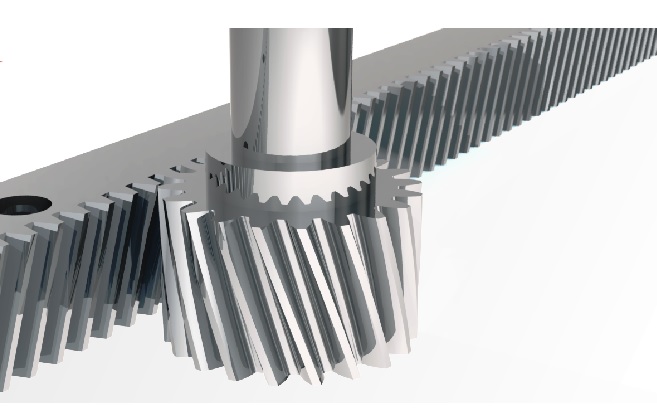
The teeth are the essential components of a helical gear rack. Unlike straight gear racks, the teeth of a helical gear rack are cut at an angle or helix to the rack’s axis. The helical teeth have a curved shape, resembling the teeth of a helical gear. The helical tooth design provides several advantages, including smoother operation, reduced noise, and improved load distribution.
3. Tooth Profile:
The tooth profile of a helical gear rack determines the shape and dimensions of the teeth. It is carefully designed to ensure proper engagement and meshing with the mating gear. The tooth profile includes parameters such as the tooth height, tooth thickness, tooth angle, and pitch. The tooth profile is crucial for achieving accurate and reliable motion transmission between the rack and the mating gear.
4. Pitch:
The pitch of a helical gear rack refers to the distance between corresponding points on adjacent teeth, measured along the pitch line. It determines the linear travel distance of the rack per revolution of the mating gear. The pitch of a helical gear rack is crucial for achieving precise linear motion control and synchronization with the mating gear.
5. Helix Angle:
The helix angle is the angle at which the teeth of a helical gear rack are cut relative to the rack’s axis. It determines the direction and inclination of the teeth. The helix angle is typically specified in degrees and affects the smoothness of operation, load distribution, and axial thrust forces generated by the gear rack.
6. Mating Gear:
The helical gear rack is designed to engage with a mating gear to transmit motion. The mating gear is typically a helical gear that meshes with the teeth of the rack. The design and specifications of the mating gear must be compatible with the helical gear rack to ensure proper meshing, efficient power transmission, and reliable motion control.
7. Mounting and Support:
The helical gear rack requires appropriate mounting and support to ensure stability and proper alignment. Mounting brackets or fixtures are used to secure the rack to the machine or system framework. The support structure should be rigid and capable of withstanding the forces and loads exerted on the gear rack during operation.
In summary, the primary components and design features of a helical gear rack include the rack body, helical teeth, tooth profile, pitch, helix angle, mating gear, and mounting/support structure. These components and features work together to provide smoother operation, reduced noise, improved load distribution, and precise linear motion control in applications where a helical gear rack is employed.


editor by Dream 2024-04-25