Product Description
We are a professional company in bulk material handling, transportation, storage, processing, accessory equipment design, integration and manufacturing. We can provide a complete set of solutions. Thank you for reading the information and welcome to purchase! Welcome to agent distribution!
Brief introduction of the company’s manufacturing capacity
The company’s headquarters, technology and sales are located in Lingang New Area of China (ZheJiang ) pilot free trade zone,The company’s manufacture base is located in Xihu (West Lake) Dis. county, ZHangZhoug Province, which is known as “the most beautiful county in China”. It is 65 kilometers away from HangZhou city and 60 kilometers away from Qiandao Lake. The transportation to Xihu (West Lake) Dis. county from other places is very convenient. No matter by railway, highway or waterway. The manufacture base has a total plant area of around 30000 square CHINAMFG and workshop is equipped with more than 300 sets of various advance manufacture equipment, including 20 sets of CNC precision vertical lathe MODEL: SMVTM12000×50/150, CNC vertical lathe MODEL:DVT8000×30/32, CNC horizontal lathe, MODEL: CK61315×125/32, CNC horizontal lathe MODEL:CK61200×80/32, CNC Grounding boring and milling machine MODEL:TJK6920,etc.Most of the parts are machined by using CNC machine equipment. Theis is a hot treatment CHINAMFG with size 10.5m×8m×8m. The manufacture base also equipped with lifting capacity of 25t, 50t, 100t, 200t overhead crane to handle heavy workpiece and assembly work.
Metalworking equipment
| Name of equipment | Model number | Quantity | SCOPE of application | |
| A | Lathes | |||
| 1 | Vertical Lathe | Numerical control | 1 | Φ 12000 |
| 2 | Vertical Lathe | Numerical control | 1 | Φ 8000 |
| 3 | Vertical Lathe | 1 | Φ 1600 | |
| 4 | Vertical Lathe | C5112A | 1 | Ф 1250 |
| 5 | Horizontal Lathe | Numerical control | 1 | CK61315×12×100T |
| 6 | Horizontal Lathe | CW61200 | 1 | Ф 2000×8000 |
| 7 | Horizontal Lathe | CW61160 | 1 | Ф 1600×6500 |
| 8 | Horizontal Lathe | CW6180 | 2 | Ф 800×3000 |
| 9 | Horizontal Lathe | CW61125 | 2 | Ф 1250×5000 |
| 10 | Horizontal Lathe (remodel) | CW62500 | 2 | Ф 2800×6000 |
| 11 | Common Lathe | CY6140 | 3 | Ф 400×1000 |
| 12 | Common Lathe | CA6140 | 3 | Ф 400×1500 |
| 13 | Common Lathe | C620 | 2 | Ф 400×1400 |
| 14 | Common Lathe | C616 | 1 | Ф 320×1000 |
| 15 | Common Lathe | C650 | 1 | Ф 650×2000 |
| B | Drilling machine | |||
| 1 | Radial drilling machine | Z3080 | 3 | Ф 80×2500 |
| 2 | Radial drilling machine | Z3040 | 2 | Ф 60×1600 |
| 3 | Universal drilling machine | ZW3725 | 3 | Ф 25×880 |
| C | Planing machine | |||
| 1 | Shaper | B665 | 1 | L650 |
| 2 | Hydraulic Shaper | B690 | 1 | L900 |
| 3 | Gantry Planer | HD–16 | 1 | L10000×B1600 |
| D | Milling Machine | |||
| 1 | 4 Coordinate Milling Machine | Numerical control | 1 | 2500×4000 |
| 2 | Gantry milling machine | Numerical contro | 1 | 16mx5mx3m |
| 3 | Gantry milling machine | Numerical contro | 1 | 12mx4mx2.5m |
| 4 | Gantry milling and boring machine | Numerical contro | 1 | Φ 250 |
| 5 | Vertical Milling Machine | XS5054 | 1 | 1600×400 |
| 6 | Horizontal Milling Machine | C62W | 1 | 1250×320 |
| 7 | Horizontal Milling Machine | X60 | 1 | 800×200 |
| 8 | Gantry milling machine | X2014J | 1 | L4000×B1400 |
| 9 | Gantry milling machine | X2571J | 1 | L3000×B1000 |
| 10 | Floor end milling | TX32-1 | 1 | L1500×H800 |
| E | Grinding machine | |||
| 1 | External Grinder | M131W | 1 | Ф 300×1000 |
| 2 | External Grinder | M1432B | 1 | Ф 320×15000 |
| 3 | Surface Grinder | M7130 | 1 | L 1000×300 |
| 4 | Tool grinder | M6571C | 1 | Ф 250 |
| F | Boring machine | |||
| 1 | Floor-standing milling and boring machine | TJK6920 | 1 | X12000 × Y4500 × Z1000 |
| 2 | Boring machine | TSPX619 | 1 | Ф 1000 |
| 3 | Boring machine | T616 | 1 | Ф 800 |
| 4 | Boring machine | T611 | 1 | Ф 800 |
| G | Slotted bed | |||
| 1 | Slotted bed | B5032 | 1 | H320 |
| H | Other machine tools | |||
| 1 | Gear hobbing machine | Y3150 | 1 | Ф 500 M=6 |
| 2 | Hacksaw machine | G7571 | 1 | Ф 220 |
Products and services available
Material handling equipment
Storage equipment
Conveying equipment
Feeding equipment
Component of conveying system
Belt conveyor parts
Large and medium sized finishing parts
If you need above products, please contact us!
ZheJiang Sunshine Industrial Technology Co. , Ltd.
/* January 22, 2571 19:08:37 */!function(){function s(e,r){var a,o={};try{e&&e.split(“,”).forEach(function(e,t){e&&(a=e.match(/(.*?):(.*)$/))&&1
| Application: | Motor, Electric Cars, Motorcycle, Machinery, Marine, Toy, Agricultural Machinery, Car, Customization |
|---|---|
| Hardness: | Customization |
| Gear Position: | Customization |
.shipping-cost-tm .tm-status-off{background: none;padding:0;color: #1470cc}
|
Shipping Cost:
Estimated freight per unit. |
about shipping cost and estimated delivery time. |
|---|
| Payment Method: |
|
|---|---|
|
Initial Payment Full Payment |
| Currency: | US$ |
|---|
| Return&refunds: | You can apply for a refund up to 30 days after receipt of the products. |
|---|

What is the purpose of using helical gears in power transmission?
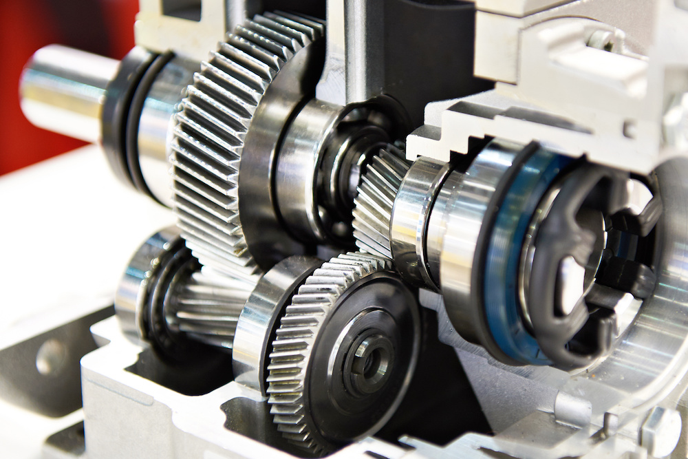
Helical gears are commonly used in power transmission systems for various purposes. Here’s a detailed explanation of the purpose and advantages of using helical gears in power transmission:
- Smooth and Efficient Power Transfer: One of the primary purposes of using helical gears in power transmission is to achieve smooth and efficient transfer of power. The inclined tooth profile of helical gears allows for gradual and continuous engagement of teeth, minimizing shock loads and ensuring a more uniform distribution of force. This results in smoother power transmission with reduced noise, vibration, and wear.
- High Torque Transmission: Helical gears are known for their high torque-carrying capacity. The inclined teeth of helical gears enable a larger tooth contact area compared to other gear types such as spur gears. This increased tooth contact area allows helical gears to transmit higher torque, making them suitable for applications that require the transfer of large amounts of power, such as in industrial machinery, automotive drivetrains, and heavy-duty equipment.
- Variable Speed Ratios: Helical gears can be designed with different numbers of teeth and varying helix angles, allowing for a wide range of speed ratios. By selecting the appropriate combination of gears, the rotational speed and torque can be adjusted to meet the requirements of the power transmission system. This flexibility in speed ratios makes helical gears versatile in applications where variable speed control is necessary.
- Reduction of Noise and Vibration: The inclined tooth profile and gradual engagement of helical gears contribute to the reduction of noise and vibration in power transmission systems. Compared to spur gears, helical gears generate less noise and vibration due to their smoother meshing characteristics and improved load distribution. This makes helical gears particularly beneficial in applications where noise reduction and smooth operation are important considerations, such as in automotive transmissions and precision equipment.
- Compact Design: Helical gears can achieve high gear ratios within a relatively compact design. The inclined teeth of helical gears allow for more teeth to be in contact at any given time, enabling a higher gear ratio compared to spur gears of the same size. This compactness is advantageous when there are space constraints or when a smaller gear mechanism is desired without sacrificing performance or torque capacity.
- High Reliability and Durability: Helical gears are designed to distribute the load over multiple teeth, resulting in improved load-carrying capacity and enhanced gear strength. The inclined tooth profile allows for a larger contact area, reducing stress concentrations and increasing the gear’s resistance to wear and fatigue. These factors contribute to the high reliability and durability of helical gears, making them suitable for demanding power transmission applications that require long service life.
In summary, the purpose of using helical gears in power transmission is to achieve smooth and efficient power transfer, high torque transmission, variable speed control, noise and vibration reduction, compact design, and high reliability. These advantages make helical gears widely used in various industries, including automotive, manufacturing, energy, and many other applications that require reliable and efficient power transmission.

How do you address noise and vibration issues in a helical gear system?
In a helical gear system, addressing noise and vibration issues is crucial to ensure smooth and quiet operation, minimize component wear, and enhance overall system performance. Here’s a detailed explanation of how to address noise and vibration issues in a helical gear system:
- Proper Gear Design: The design of the helical gears can significantly impact noise and vibration levels. Design considerations such as the helix angle, tooth profile modification, and gear tooth contact pattern optimization can help minimize gear noise and vibration. A well-designed gear system with proper tooth geometry and accurate alignment reduces the likelihood of gear meshing irregularities that contribute to noise and vibration.
- Precision Manufacturing: High-quality manufacturing processes are essential to minimize noise and vibration in helical gear systems. Precise gear cutting techniques, such as hobbing or grinding, ensure accurate tooth profiles, which help reduce gear meshing deviations and associated noise. Additionally, maintaining tight manufacturing tolerances and surface finishes on gear components can help minimize vibration caused by irregularities or imperfections.
- Alignment and Assembly: Proper alignment and assembly of the helical gears are critical to minimize noise and vibration. Ensuring precise alignment of the gear shafts and gear meshing is essential to achieve optimal contact between the gear teeth. The use of alignment tools, such as dial indicators or laser alignment systems, can aid in achieving accurate alignment. Additionally, proper assembly techniques, including appropriate gear backlash and preload adjustment, can help minimize noise and vibration by optimizing gear meshing conditions.
- Optimal Lubrication: Proper lubrication is vital for reducing noise and vibration in a helical gear system. Adequate lubrication creates a thin film between the gear teeth, minimizing friction and wear. The lubricant also helps to dampen vibrations and dissipate heat generated during gear operation. Using the correct lubricant type, viscosity, and maintaining proper lubricant levels are essential for noise and vibration control.
- Stiffness of Gearbox Housing: The stiffness and rigidity of the gearbox housing influence noise and vibration levels in a helical gear system. A robust and well-designed housing structure helps to minimize the transmission of vibrations from the gears to the surrounding environment. It is important to ensure that the gearbox housing is adequately braced and supported to reduce resonances and vibrations that can contribute to noise.
- Vibration Damping: Implementing vibration damping techniques can help mitigate noise and vibration in a helical gear system. This can include the use of vibration-absorbing materials, such as elastomers or damping pads, at appropriate locations within the gear system. These materials help absorb and dissipate vibrations, reducing noise transmission and minimizing gear system resonance.
- Condition Monitoring and Maintenance: Regular condition monitoring and maintenance practices are essential for identifying and addressing noise and vibration issues in a helical gear system. Periodic inspections, including vibration analysis, can detect any abnormal vibration patterns or wear indications. Timely maintenance, such as addressing misalignment, worn components, or inadequate lubrication, can prevent further deterioration and reduce noise and vibration levels.
By implementing these measures, engineers can effectively address noise and vibration issues in a helical gear system, resulting in quieter operation, reduced component wear, and improved overall system performance.

Are there different types of helical gears available?
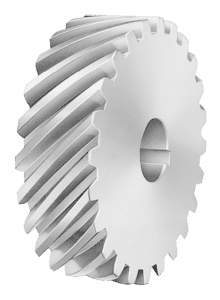
Yes, there are different types of helical gears available to meet specific application requirements. Here’s a detailed explanation of some common types of helical gears:
- Parallel Helical Gears: Parallel helical gears are the most commonly used type of helical gears. In this configuration, two helical gears with parallel axes are meshed together. They transmit power and motion between parallel shafts. Parallel helical gears provide smooth operation, high load-carrying capacity, and efficient power transmission.
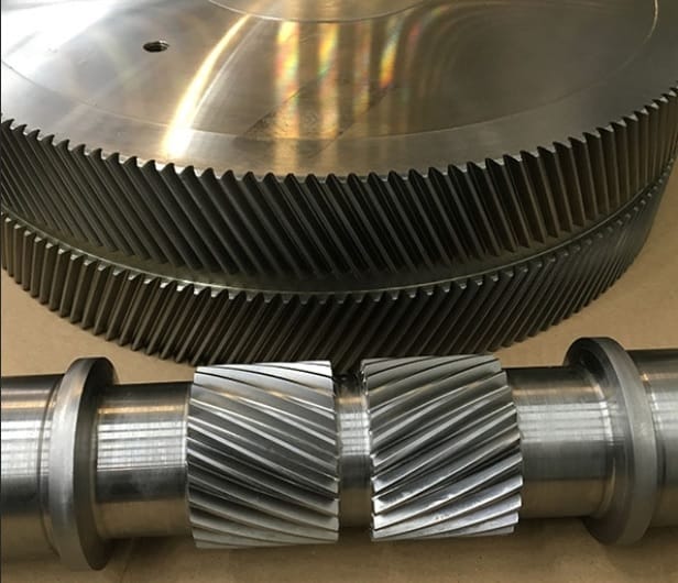
- Double Helical Gears (Herringbone Gears): Double helical gears, also known as herringbone gears, have two sets of helical teeth that are placed in a V-shaped configuration. The V-shaped teeth face each other, with a groove or gap in the middle. This design cancels out the axial thrust that is generated by the helical gear’s inclined teeth. Double helical gears are often used in applications that require high torque transmission and axial load balancing, such as heavy machinery and marine propulsion systems.
- Crossed Helical Gears (Screw Gears): Crossed helical gears, also referred to as screw gears, involve the meshing of two helical gears with non-parallel and non-intersecting axes. The gears are oriented at an angle to each other, typically 90 degrees. Crossed helical gears are used in applications where shafts intersect or when a compact and non-parallel gear arrangement is required. They are commonly found in hand drills, speedometers, and some mechanical watches.
- Skew Gears: Skew gears are a type of helical gear in which the gear teeth are cut at an angle to the gear axis. The angle of the teeth can vary, allowing for different degrees of skew. Skew gears are used in applications where the axes of the mating gears are neither parallel nor intersecting. They can transmit power between non-parallel and non-intersecting shafts while accommodating misalignments.
- Helical Rack and Pinion: A helical rack and pinion system consists of a helical gear (pinion) that meshes with a linear gear (rack). The pinion is a cylindrical gear with helical teeth, while the rack is a straight bar with teeth that mesh with the pinion. This configuration is commonly used in applications that require linear motion, such as CNC machines, robotics, and rack and pinion steering systems in automobiles.
- Variable Helix Gears: Variable helix gears have a unique tooth profile where the helix angle varies along the face width of the gear. The varying helix angle helps to reduce noise, vibration, and backlash while maintaining smooth operation and load distribution. These gears are often used in high-performance applications where noise reduction and precise motion control are critical.
The specific type of helical gear used depends on factors such as the application requirements, load conditions, space limitations, and desired performance characteristics. Manufacturers often provide various options and customizations to meet specific needs.
It’s important to note that the design and manufacturing of helical gears require careful consideration of factors such as tooth profile, helix angle, lead angle, module or pitch, pressure angle, and material selection. These factors ensure proper gear meshing, load distribution, and efficient power transmission.
In summary, different types of helical gears, including parallel helical gears, double helical gears (herringbone gears), crossed helical gears (screw gears), skew gears, helical rack and pinion systems, and variable helix gears, are available to cater to a wide range of applications. Each type has its unique characteristics and advantages, allowing for optimized performance and reliable power transmission in various industries and machinery.


editor by Dream 2024-04-19